Compact power running board

a running board and compact technology, applied in the direction of railway components, steps, vehicle components, etc., can solve the problem of increasing assembly weight, and achieve the effect of reducing backlash of running boards

Active Publication Date: 2019-07-09
MAGNA INTERNATIONAL INC
View PDF21 Cites 20 Cited by
  • Summary
  • Abstract
  • Description
  • Claims
  • Application Information

AI Technical Summary

Benefits of technology

[0007]A pivot shaft is located within a housing, and the linkage includes a drive arm connected to the pivot shaft within the housing at a predetermined location on the pivot shaft between two bushings that are coupled to the pivot shaft within the housing. The bushings are spaced an operable predetermined distance apart from each other and with the swing arm at a predetermined location therebetween, which provides an improved balanced force condition since the bushing and housing reaction forces are significantly reduced. Another pivot shaft is located within another housing, and the linkage also includes an idler arm connected to the pivot shaft within that housing. Two bushings are also coupled to the pivot shaft within the housing with the idler arm coupled therebetween on the pivot shaft. The actuator is operably coupled to the linkage to cause rotation of the linkage to move the running board between the at least one stowed position and at least one deployed position. The attachment locations of the drive arm and idler arm within the respective housings between the at least two bushings, respectively, provides a compact, reduced height package for smaller clearance vehicles. The arrangement also allows for a smaller housing to significantly reduce the weight of the compact running board assembly.
[0011]According to yet another aspect of the invention, a running board assembly for a motor vehicle includes a mounting bracket adapted for attachment to the motor vehicle, a running board movable relative to the mounting bracket between a stowed position tucked underneath the motor vehicle, a cab entry position disposed generally outwardly from the motor vehicle, and a box side step position disposed generally outwardly from the motor vehicle and generally rearward to the cab entry position, a motor operably coupled to the running board for driving movement thereof, and an electronic control unit electronically connected to the motor and programmed to turn off said motor when said running board reaches said cab entry position. The running board assembly also includes a housing assembly including a worm member operably coupled to the motor. The housing assembly includes a zero backlash worm self locking member, to eliminate backlash of the running board when the running board is in the cab entry position, having a worm gear fixedly mounted on an end of a ball screw and a ball nut mounted along the ball screw for movement relative thereto.

Problems solved by technology

To avoid high internal forces and stresses, this cantilever structure also requires a larger housing, which increases the weight of the assembly.

Method used


Image

  • Compact power running board
  • Compact power running board
  • Compact power running board

Examples


Embodiment Construction

[0038]The following description of the preferred embodiment(s) is merely exemplary in nature and is in no way intended to limit the invention, its application, or uses.

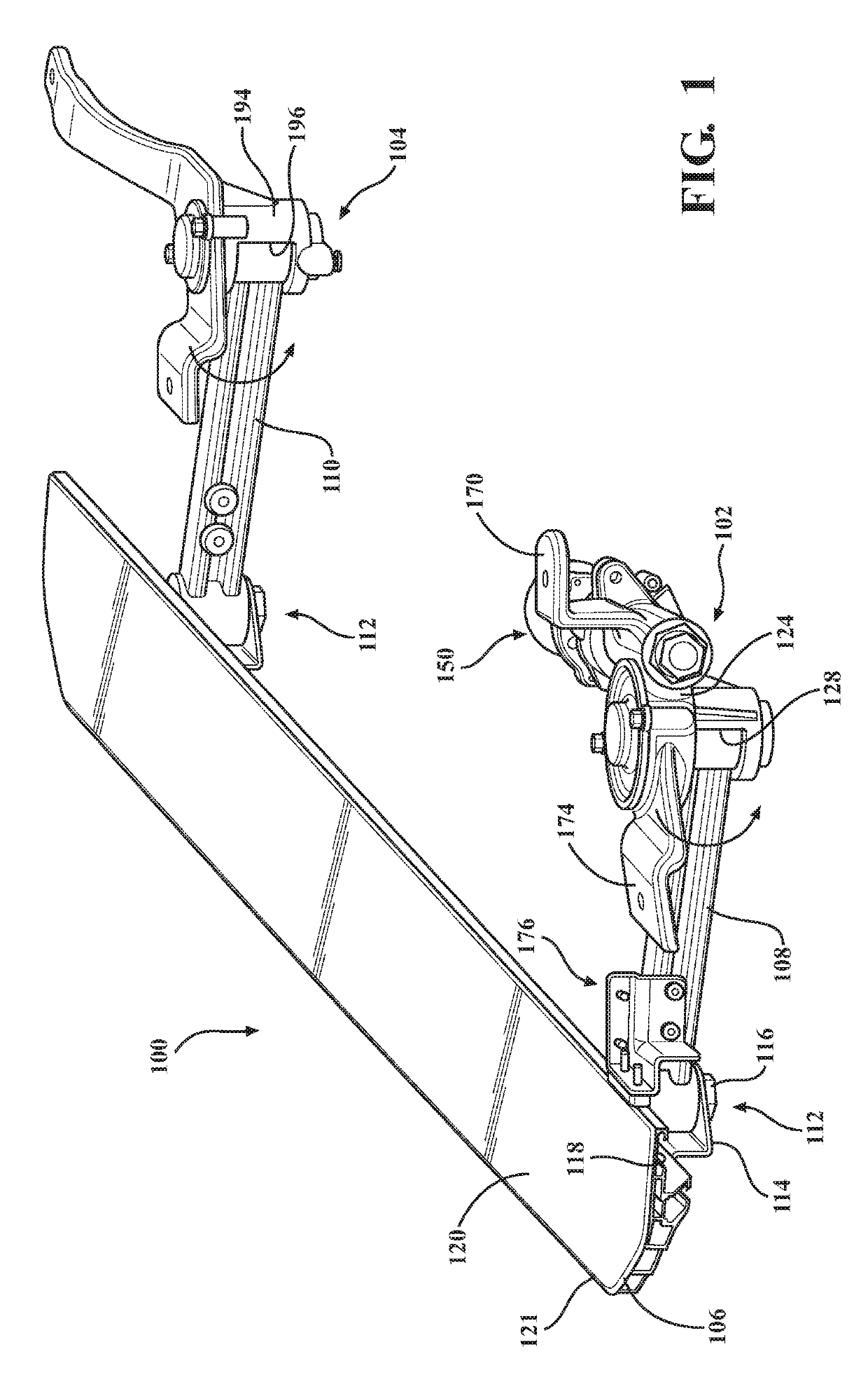
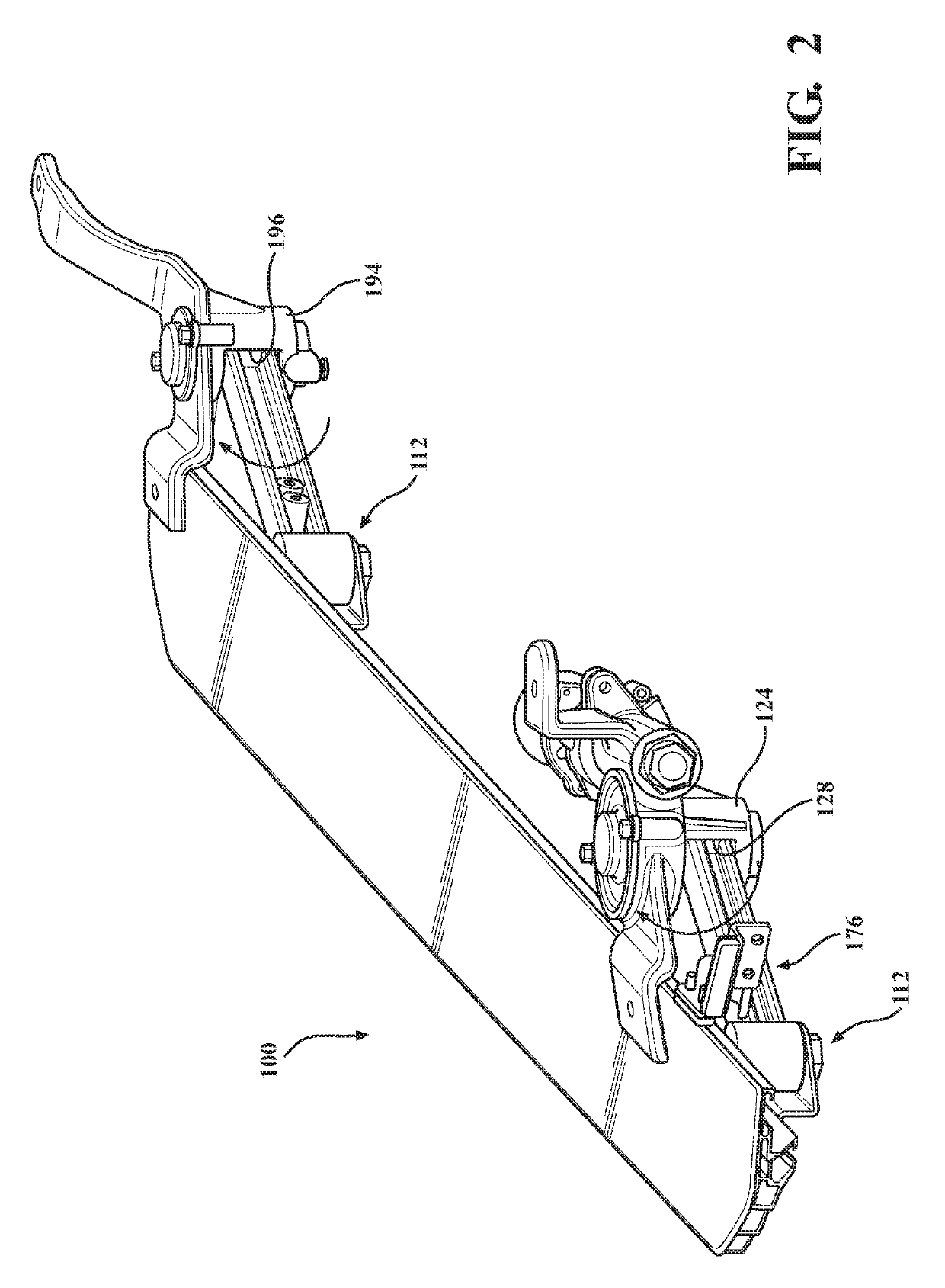
[0039]Referring to FIGS. 1-12 generally, there is provided a compact power running board assembly, shown generally at 100, according to the present invention, including at least one drive swing arm mechanism, shown generally at 102, and at least one idler swing arm mechanism, shown generally at 104. A running board 106 is connected to a first swing arm 108 (or “pivot linkage” or “drive arm”) of the drive swing arm mechanism 102 and to a second swing arm 110 of the idler swing arm mechanism 104 at outboard pivot sub-assemblies indicated generally at 112 (“pivot sub-assemblies”).

[0040]The pivot sub-assemblies 112,112 are arranged generally vertically in the motor vehicle installed position. Alternative arrangements are contemplated depending on the application without departure from the scope of the present invention. P...


PUM


Abstract

A compact deployable / retractable running board assembly for a motor vehicle including a running board, linkage coupled to the running board, and a motor assembly coupled to an actuator, the running board moveable between at least one stowed position and at least one deployed position. The linkage includes a drive arm connected to a pivot shaft within a housing at a location on the pivot shaft between two bushings that are coupled to the pivot shaft within the housing. The linkage also includes an idler arm connected to a pivot shaft within an idler housing. The actuator is operably coupled to the linkage to cause rotation of the linkage to move the running board between the at least one stowed position generally under the motor vehicle and at least one deployed position to provide a step surface for a user.

Description

CROSS-REFERENCE TO RELATED APPLICATIONS[0001]This application is a continuation-in-part of U.S. patent application Ser. No. 15 / 481,637, filed Apr. 7, 2017, which is a continuation of U.S. patent application Ser. No. 14 / 807,070, filed Jul. 23, 2015, issued as U.S. Pat. No. 9,649,983, which claims the benefit of U.S. Provisional Application No. 62 / 028,006, filed Jul. 23, 2014. The disclosures of the above applications are incorporated herein by reference.FIELD OF THE INVENTION[0002]The present invention relates to a compact structure for use in a power running board system for automotive applications.BACKGROUND OF THE INVENTION[0003]Known power running boards have a large, high package size suitable for larger vehicles such as pickup trucks. These boards are generally moveable to gain access to passenger cabs and / or a cargo bed box. Parallel swing arms are typically connected on the outside of respective housings to pivot shaft ends, which increases the overall height of the assembly....

Claims


Application Information

Patent Timeline
Patent Type & Authority Patents(United States)
IPC IPC(8): B60R3/02B60R3/00B61D23/02
CPCB60R3/02B60R3/002B61D23/02B61D23/025
Inventor LONG, ALBERT YUGUANGJOHNSON, JEFFREY R.WATSON, BRADLEY E.
Owner MAGNA INTERNATIONAL INC
Why Eureka
Try Eureka