Hydraulic inert container device

A kind of inerter and hydraulic technology, applied in the direction of mechanical equipment, etc., can solve the problems of tooth overload breaking, adjacent teeth cannot be effectively contacted, hysteresis phase, etc., and achieve the effect of eliminating backlash

Active Publication Date: 2011-02-16
JIANGSU UNIV
View PDF5 Cites 22 Cited by
  • Summary
  • Abstract
  • Description
  • Claims
  • Application Information

AI Technical Summary

Problems solved by technology

[0005] Although rack and pinion inerters are easy to design, the backlash (backlash) between the teeth when the gears mesh is a serious problem
The backlash will cause the two adjacent teeth to not be in effective contact during the rotation process. Due to the existence of the backlash, it will cause hysteresis and phase lag during high-speed rotation and commutation
What's more serious is that under the heavy load of the rack and pinion container, the teeth are easily broken due to short-term overload or impact load.

Method used


Image

  • Hydraulic inert container device
  • Hydraulic inert container device
  • Hydraulic inert container device

Examples


Embodiment 1

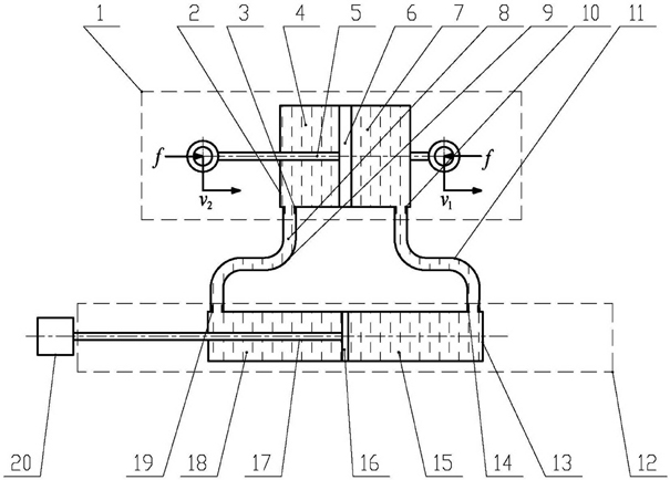
[0027] The present invention includes a large hydraulic cylinder 1, a small hydraulic cylinder 12, a quality block A20, a high-pressure hose A9 and a high-pressure hose B11.

[0028] Large hydraulic cylinder 1 includes cylinder A2, piston A6 placed in cylinder A2 and piston rod A5 connected with piston A6. Piston A6 divides cylinder A2 into two chambers, chamber A4 and chamber B7. The chamber A4 is close to the cylinder An oil port A3 is provided at the end of the body A2, an oil port B10 is provided in the chamber B7 close to the end of the cylinder A2, and the piston rod A5 protrudes from one end of the chamber A4 of the cylinder A2.

[0029] The small hydraulic cylinder 12 includes a cylinder B13, a piston B16 placed in the cylinder B13, and a piston rod B17 connected to the piston B16. The piston B16 divides the cylinder B13 into two chambers, chamber C15 and chamber D18, and the chamber C15 is close to the cylinder. An oil port C14 is provided at the end of the body B13, ...

Embodiment 2

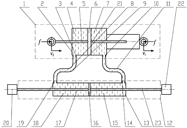
[0034] The difference between the second embodiment and the first embodiment is that a piston rod C21 is added to the cavity B7 of the large hydraulic cylinder 1 in the second embodiment, one end of the piston rod C21 is connected with the piston A6, and the other end is connected to the large hydraulic cylinder 1. The cavity B7 of the small hydraulic cylinder 12 extends out, and a piston rod D23 is added in the cavity C15 of the small hydraulic cylinder 12. One end of the piston rod D23 is connected with the piston B16, and the other end protrudes from the cavity C15 of the small hydraulic cylinder 12 and is connected with the added mass B22 . Other parts of the hydraulic inerter device are all exactly the same as cylinder block A2, cylinder block B13, piston A6, piston B16, high-pressure hose A9 and high-pressure hose B11.

[0035]The specific implementation process of the present invention will be further described below in conjunction with the accompanying drawings.

[00...


PUM


Abstract

The invention relates to a hydraulic inert container device, which comprises a big hydraulic cylinder, a small hydraulic cylinder and a mass block. The two cavities of the big hydraulic cylinder and the two cavities of the small hydraulic cylinder are correspondingly communicated; and the mass block is connected with the end of a piston rod of the small hydraulic cylinder. When external force is applied to the piston rod and the cylinder body of the big hydraulic cylinder along the axial direction of the piston rod, the piston moves linearly relative to the cylinder body and pushes the oil toflow into the small hydraulic cylinder from the big hydraulic cylinder so as to form pressure difference between the two sides of the piston in the small hydraulic cylinder; and the pressure difference drives the piston of the small hydraulic cylinder to move and finally drives the mass block to move so as to obtain the characteristics of the inert container. Force transferring liquid is arrangedin the hydraulic inert container device, and only by adding a proper damping mechanism to the liquid passage, the device can be used as a damping element as well, thereby saving additional special damping element for the system. The invention provides an ideal inert container device capable of bearing big load and serving as a damping element for a vibration system.

Description

Technical field [0001] The present invention involves a container device, which refers to the liquid tolerant container device. Background technique [0002] Electromechanical integration has become an important development direction in the field of engineering in the new century.In this integrated process, it is often necessary to network mechanical and electronic systems as a large system to study.In traditional engineering applications, there are two corresponding relationships with the electronic system, one is the "force-voltage" corresponding, that is, the quality, damping, and the spring respectively correspond to the inductance, resistance and capacitance., That is, quality, damping, and spring corresponding to the capacitance, resistance and inductance, respectively. [0003] The above -mentioned electronic network components have two independent and free endpoints, that is, both endpoints of inductors, resistors and capacitors are not limited by specific reference point...

Claims


Application Information

Patent Timeline
Patent Type & Authority Applications(China)
IPC IPC(8): F15B1/04
Inventor 陈龙张孝良聂佳梅汪若尘江浩斌
Owner JIANGSU UNIV
Why Eureka
Try Eureka