
Method for compensating infrared photography positioning by using acceleration sensor

An acceleration sensor, infrared camera technology, applied in the direction of instruments, optical devices, measuring devices, etc., can solve the problems of vertical downward movement, inconsistent movement direction of wireless control device and positioning movement direction, etc.

Inactive Publication Date: 2013-02-13
CHINA HUALU GRP
View PDF3 Cites 5 Cited by
  • Summary
  • Abstract
  • Description
  • Claims
  • Application Information

AI Technical Summary

Problems solved by technology

[0003] However, the positioning function of the existing wireless control device can only locate the mobile position of the wireless control device when it is held horizontally through the acceleration of gravity sensor and the camera. There is a situation where the movement direction of the wireless control device is inconsistent with the positioning movement direction. For example, when the wireless control device is turned over and the wireless control device is held to move vertically upward, the positioning display is vertically downward.

Method used


Image

  • Method for compensating infrared photography positioning by using acceleration sensor
  • Method for compensating infrared photography positioning by using acceleration sensor
  • Method for compensating infrared photography positioning by using acceleration sensor

Examples

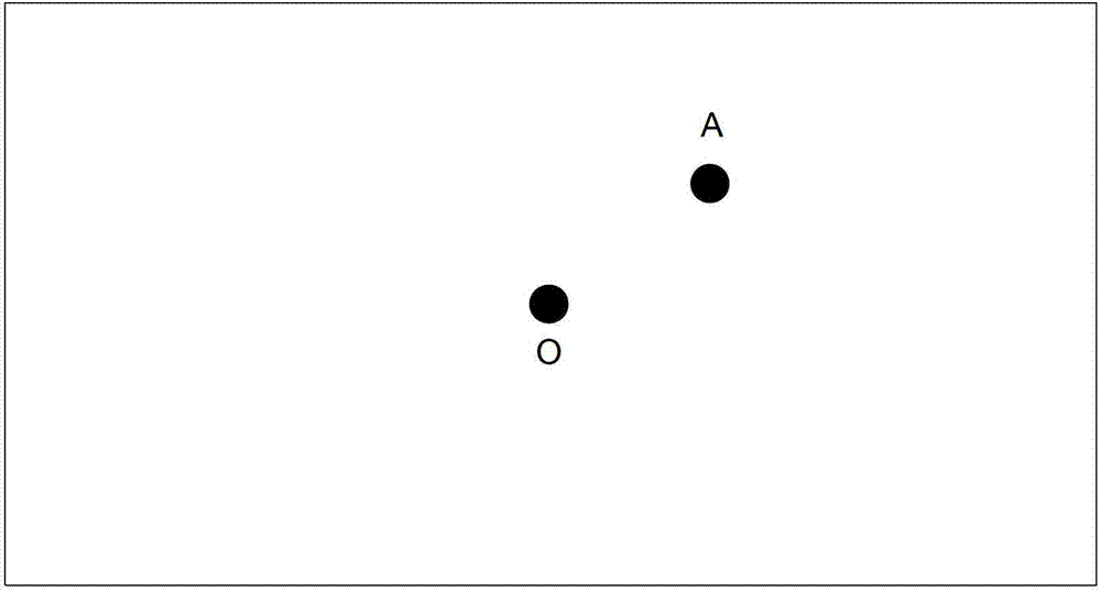

Embodiment Construction

[0021] The present invention provides a method for using an acceleration sensor to compensate for infrared camera positioning, and the technical solution of the present invention will be described below in conjunction with the accompanying drawings.

[0022] A method for using an acceleration sensor to compensate for infrared camera positioning, characterized in that it comprises the following steps:

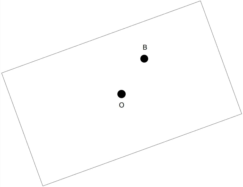
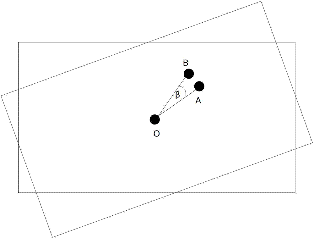
[0023] S1. Obtain the rotation angle β of the wireless control device relative to the horizontal direction through the acceleration of gravity sensor;

[0024] S2. Obtain the position B (XO, YO) of the target positioning point before correction through the camera;

[0025] S3. Correct the target positioning point through the infrared camera positioning unit: set the position of the corrected target positioning point as point A (X, Y), and set the polar coordinates of point A as (ρ, α), where ρ is A The distance between the point and the origin O, that is, the length of OA, α is...


PUM


Abstract

The invention discloses a method for compensating infrared photography positioning by using an acceleration sensor, which comprises the following steps of: S1, acquiring the rotation angle beta which is relative to a horizontal direction, of a wireless control device through a gravitational acceleration sensor; S2, acquiring the position B point (XO, YO) of a target positioning point which is not corrected through a camera; S3, correcting the target positioning point through an infrared photography positioning unit; and S4, acquiring a corrected target positioning point A (X0cosbeta-Y0sinbeta, Y0cosbeta+X0sinbeta) so that the wireless control device can accurately position the target positioning point under the condition of rotating at the beta angle relative to the horizontal direction. According to the invention, the target positioning point is corrected through the infrared photography positioning unit so that the wireless control device can accurately position the target positioning point under the condition of rotating at the beta angle relative to the horizontal direction.

Description

technical field [0001] The invention relates to a positioning compensation method of a wireless control device used in the fields of game machines, smart TVs, and smart set-top boxes, and more specifically, relates to a method of using an acceleration sensor to compensate infrared camera positioning. Background technique [0002] At present, more and more wireless control devices are used in the field of smart TVs and TV game consoles to complete complex information interaction tasks, such as positioning and motion recognition. To accomplish the aforementioned tasks, the wireless control device should have modules such as a gravity acceleration sensor, a camera, wireless communication, and a feature recognition illuminant. The existing wireless control device can perceive the motion state information of the three-dimensional space of the wireless control device at all times through the perception of the acceleration of gravity sensor. Then, the coordinate transformation of ...

Claims


Application Information

Patent Timeline
Patent Type & Authority Applications(China)
IPC IPC(8): G01B21/00G01B11/00
Inventor 封连重张丽坤
Owner CHINA HUALU GRP
Learn More