Limiting locking device

A locking device and limit technology, which is used in measurement devices, instruments, aerodynamic tests, etc., can solve the problems of poor wind tunnel test safety, large vibration response of the full-motion airfoil model, and full-motion airfoil model and wind tunnel test. Equipment damage and other problems, to reduce the probability of damage and improve safety

Inactive Publication Date: 2013-02-13
INST OF HIGH SPEED AERODYNAMICS OF CHINA AERODYNAMICS RES & DEV CENT +1
View PDF8 Cites 12 Cited by
  • Summary
  • Abstract
  • Description
  • Claims
  • Application Information

AI Technical Summary

Problems solved by technology

Since there is no limit locking device, the vibration response of the full-motion airfoil model is very likely to be too large, resu

Method used


Image

  • Limiting locking device
  • Limiting locking device
  • Limiting locking device

Examples


Embodiment Construction

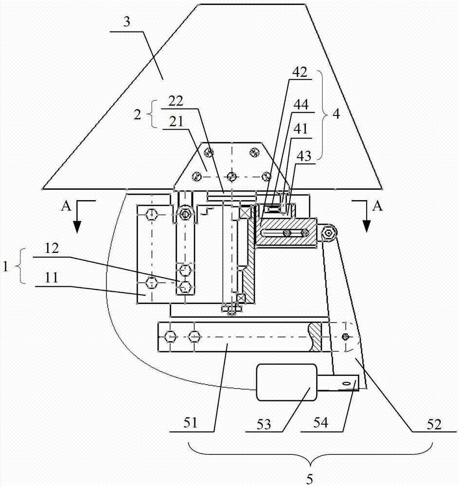
[0036] figure 1 Schematic diagram of the structure of the limit locking device provided by the embodiment of the present invention.

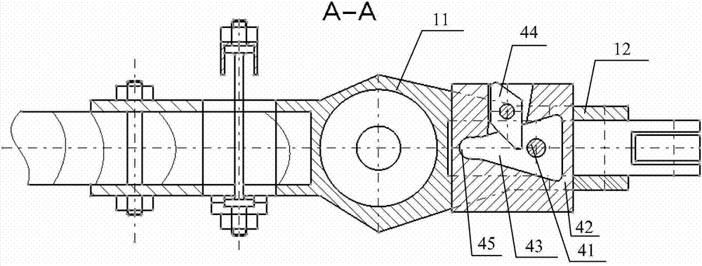
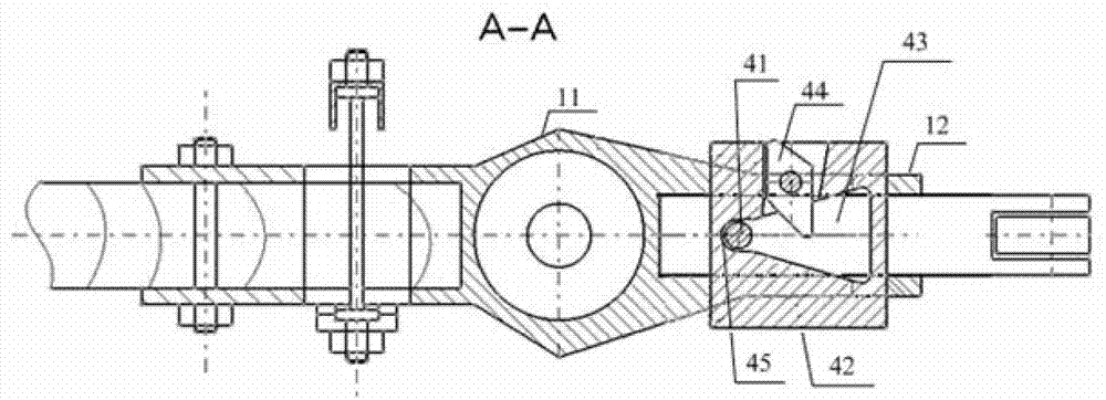
[0037] see figure 1 , the embodiment of the present invention provides a limit locking device for full-motion airfoil flutter model wind tunnel test, wherein the limit locking device includes a support part 1, a clamping part 2, a braking part 4 and a moving part 5. The supporting part 1 is used to provide support, and can be fixed with other parts such as locomotives; the clamping part 2 is rotatably connected to the supporting part 1, and the clamping part 2 is used to clamp the full-motion airfoil 3 to be tested. The clamping part 2 It can drive the full-motion airfoil 3 to rotate relative to the support part 1, and the rotation axis is in the vertical direction; the brake part 4 includes a brake lever 41 and a brake slider 42, and the brake lever 41 is used to be fixed on the full-motion airfoil 3; the brake slider 42 is slidably connecte...


PUM


Abstract

The invention provides a limiting locking device which is used for a wind tunnel test for an all moving airfoil flutter model. The limiting locking device comprises a support component, a clamping component and a brake component, wherein the support component is used for supporting; the clamping component is rotatably connected on the support component, is used for clamping a all moving airfoil to be tested, and can drive the all moving airfoil to rotate relative to the support component, wherein a rotating shaft is in the vertical direction; the brake component comprises a brake rod and a brake slider; the brake rod is fixed below the all moving airfoil; the brake slider is connected with the support component in a sliding way; an empty groove is formed in the brake slider; and the brake rod extends into the empty groove. With the adoption of the limiting locking device provided by the technical scheme, the amplitude of the all moving airfoil can be effectively limited, thus large amplitude can not suddenly occur on the all moving airfoil during test process, and the possibility that the all moving airfoil is damaged is reduced, and the testing safety is improved.

Description

technical field [0001] The invention relates to mechanical structure technology, in particular to a limit locking device. Background technique [0002] Many new aircraft currently under development have fully moving airfoils. The advantage of the full-motion airfoil is that when it is used as a rudder surface, the rudder deflection efficiency is high; but the disadvantage is that when flying at low altitude and high speed, the airfoil rotation mode may be coupled with the airfoil bending or torsional mode, thus causing a full-motion The flutter of the moving wing surface diverges, leading to flight safety accidents. Therefore, after the design of the aircraft is finalized, in order to ensure safety, it is necessary to conduct full-motion wing surface flutter model wind tunnel tests to accurately obtain the flutter safety boundary of the aircraft. [0003] In the prior art, when the full-motion airfoil flutter model wind tunnel test is carried out, the full-motion airfoil m...

Claims


Application Information

Patent Timeline
IPC IPC(8): G01M9/04
Inventor 路波金伟余立郭洪涛杨兴华罗建国吕彬彬闫昱寇西平刘靖罗太元黄飓马晓永杨贤文
Owner INST OF HIGH SPEED AERODYNAMICS OF CHINA AERODYNAMICS RES & DEV CENT
Why Eureka
Try Eureka