
Manufacturing method for super junction metal oxide semiconductor field effect transistor (MOSFET)

A manufacturing method and technology of source region, applied in semiconductor/solid-state device manufacturing, electrical components, circuits, etc., to achieve the effect of reducing production cost, increasing difficulty, and reducing quantity

Active Publication Date: 2013-02-13
XIAN LONTEN RENEWABLE ENERGY TECH +1
View PDF6 Cites 18 Cited by
  • Summary
  • Abstract
  • Description
  • Claims
  • Application Information

AI Technical Summary

Problems solved by technology

[0002]The existing super-junction MOSFET manufacturing method one is: first form a composite buffer layer, and then the same as the ordinary MOSFET manufacturing process: growth field oxygen, field oxygen etching , form the gate oxide layer (gate oxide), gate electrode (poly), form the device characteristic layer (p well region), source region n+, metal electrode, etc. The disadvantage of this method is that when forming the device characteristic layer (well region), it will There is a high-temperature annealing process, which will affect the morphology of the composite buffer layer (CB layer)

Method used


Image

  • Manufacturing method for super junction metal oxide semiconductor field effect transistor (MOSFET)
  • Manufacturing method for super junction metal oxide semiconductor field effect transistor (MOSFET)
  • Manufacturing method for super junction metal oxide semiconductor field effect transistor (MOSFET)

Examples


Embodiment Construction

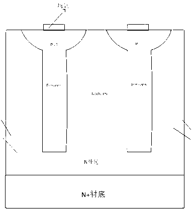
[0032] The manufacturing steps of device of the present invention are:

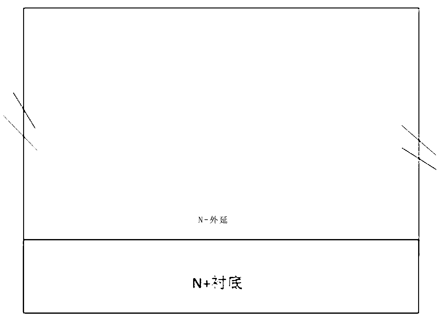
[0033] Step 1: provide n-type heavily doped n+ substrate, and form n-type epitaxial layer on n+ substrate, as figure 1 Show.

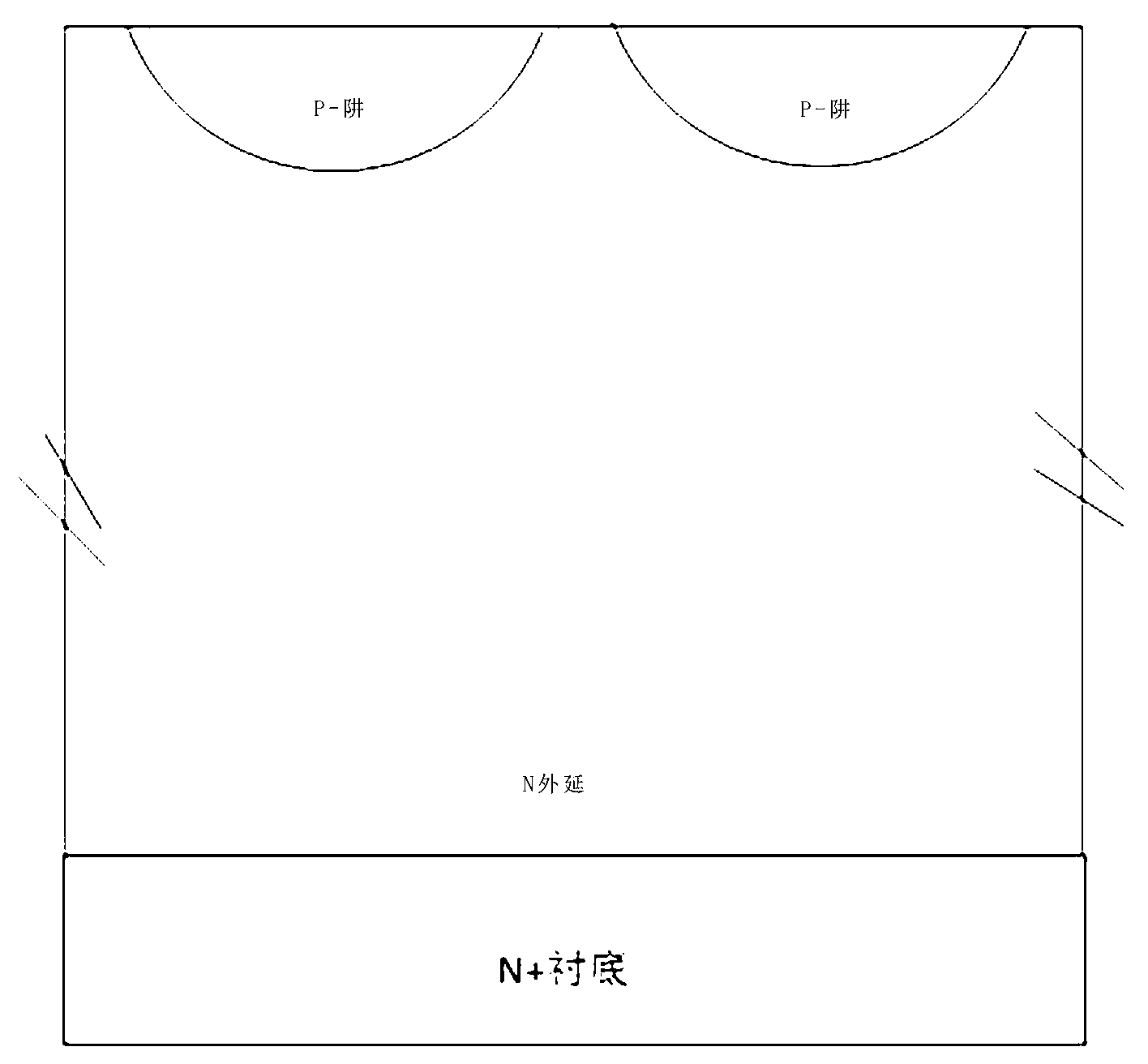
[0034] Step 2: Define the implantation region of the p-body by photolithography, perform p-type impurity implantation, and form a p-well region by thermal process push well, such as figure 2 Show.

[0035] Step 3: Define the area for forming p-columm by photolithography, and form p-column by etching and epitaxial filling to form a composite buffer layer, such as image 3 Show.

[0036] Step 4: growing a field oxide layer on the silicon wafer, Figure 4 Show.

[0037] Step 5: Define the device cell area through the photolithographic field oxide layer, and reserve part of the field oxygen as a barrier layer for n+ implantation in the source region, such as Figure 5 Show.

[0038] Step 6: growing a gate oxide layer, depositing polysilicon, and defining the region of the pol...


PUM


Abstract

The invention relates to a manufacturing method for a super junction metal oxide semiconductor field effect transistor (MOSFET). The manufacturing method is implemented by the following steps of: providing an n-type heavily-doped n+ substrate, forming an n-type epitaxial layer on the n+ substrate, and forming a p well region and a composite buffer layer; growing a field oxide layer on a silicon chip; defining a device cell region by photoetching the field oxide layer, and reserving a part of the field oxide layer as a barrier layer for the injection of a source region n+; growing a gate oxide layer, depositing polycrystalline silicon, and defining a region of a polycrystalline silicon gate in a photoetching way; using a polycrystalline silicon layer and the field oxide layer as a barrier layer for the n-type impurity ion injection of source region, and performing well driving to form the source region n+; depositing a dielectric layer on the surface of the whole semiconductor silicon chip; defining a contact hole region in a photoetching way, and etching the dielectric layer to form a contact hole; and depositing a metal layer on the dielectric layer, and performing etching. The manufacturing method can be implemented by the conventional semiconductor manufacturing process, and the increase of difficulty in the process is avoided, so that production cost is lowered.

Description

technical field [0001] The invention relates to a manufacturing method of a super junction MOSFET. Background of the invention [0002] The existing super-junction MOSFET manufacturing method one is: first form a composite buffer layer, and then the same as the ordinary MOSFET manufacturing process: grow field oxygen, field oxygen etching, form gate oxide, gate electrode (poly) , forming the device feature layer (p well region), source region n+, metal electrodes, etc. The disadvantage of this method is that there will be a high temperature annealing process when forming the device feature layer (well region), which will affect the composite buffer layer (CB layer ) shape has an impact. [0003] The second existing super junction MOSFET manufacturing method is: first form the device feature layer (p well region) on the wafer, then form the composite buffer layer (CB layer), then grow field oxygen, field oxygen etching, and form gate oxide layer (gate oxide), gate electrod...

Claims


Application Information

Patent Timeline
Patent Type & Authority Applications(China)
IPC IPC(8): H01L21/336
Inventor 陈桥梁任文珍陈仕全马治军杜忠鹏
Owner XIAN LONTEN RENEWABLE ENERGY TECH
Learn More