
Reporting method and device for wireless channel state indicator

A technology for wireless channel status and information reporting, applied in wireless communication, signaling features, electrical components, etc., can solve the problem of low CSI resource use efficiency

Active Publication Date: 2013-02-13
ZTE CORP
View PDF5 Cites 20 Cited by
  • Summary
  • Abstract
  • Description
  • Claims
  • Application Information

AI Technical Summary

Problems solved by technology

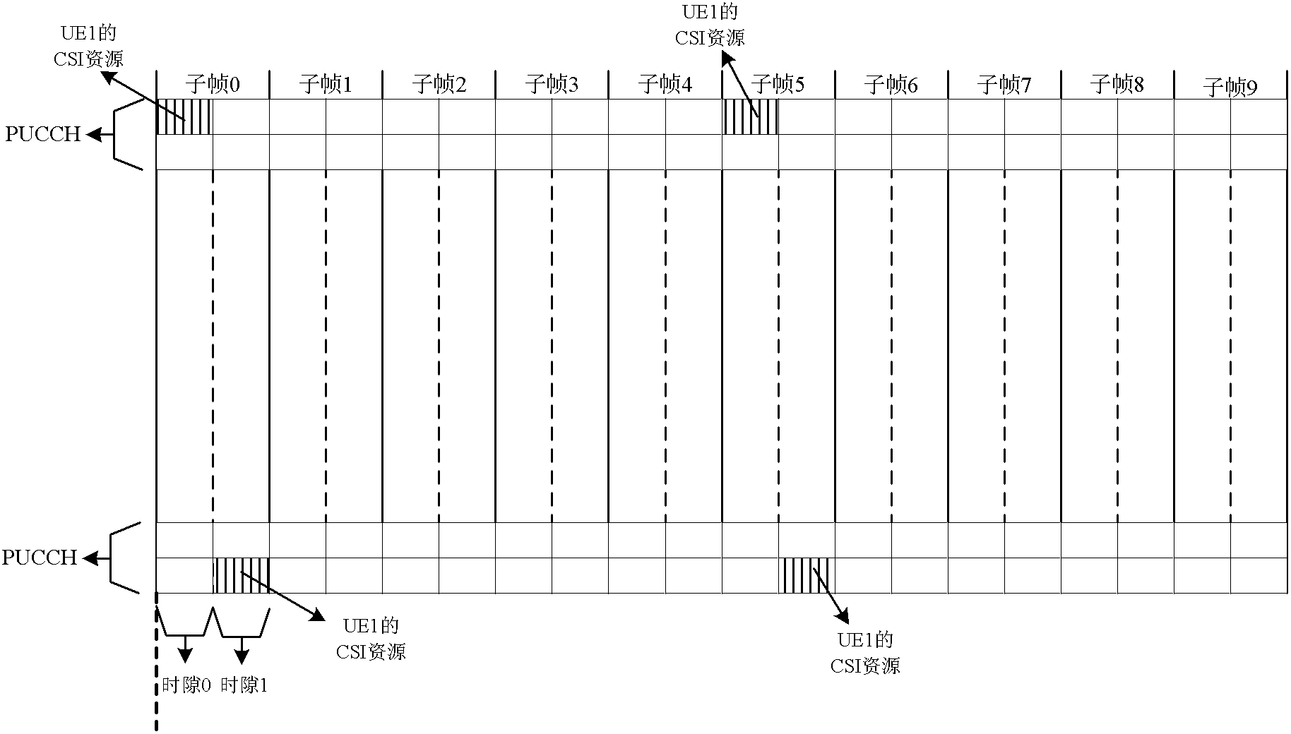
[0015] The present invention is proposed in view of the problem in the related art that the terminal has been occupying CSI resources, resulting in low efficiency of the use of CSI resources. Therefore, the main purpose of the present invention is to provide a wireless channel state information reporting method and device to solve the above problems

Method used


Image

  • Reporting method and device for wireless channel state indicator
  • Reporting method and device for wireless channel state indicator
  • Reporting method and device for wireless channel state indicator

Examples


example 1

[0047] Example 1: The network element of the access network determines the data transmission period according to the historical transmission time of the service data. Since the historical transmission time can best reflect the time distribution characteristics of business data transmission, in this preferred embodiment, the data transmission period is determined directly according to the historical transmission time of business data, the determination procedure is simple and the determination result is reliable.

example 2

[0048] Example 2: The network element of the access network receives the transmission time distribution characteristics of the service data from the terminal; the network element of the access network determines the data transmission cycle according to the transmission time distribution characteristics. Since the terminal can obtain the transmission time distribution characteristics of service data in a timely and accurate manner, the network element of the access network determines the data transmission period according to the transmission time distribution characteristics from the terminal, which can ensure that the data transmission period is closer to the current terminal situation, and then can Ensure efficient transmission of service data between network elements of the access network and terminals.

example 3

[0049] Example 3: The network element of the access network receives the transmission time distribution characteristics of the service data from the core network; the network element of the access network determines the data transmission cycle according to the transmission time distribution characteristics. Since the core network can store the transmission time distribution characteristics of multiple service data, the network element of the access network determines the data transmission cycle according to the transmission time distribution characteristics from the core network, which can ensure that the initial period of service initiation by the user (that is, there is no historical transmission Time or past transmission time distribution characteristics) determine the data transmission cycle, which can ensure the efficient transmission of service data between the access network element and the terminal.


PUM


Abstract

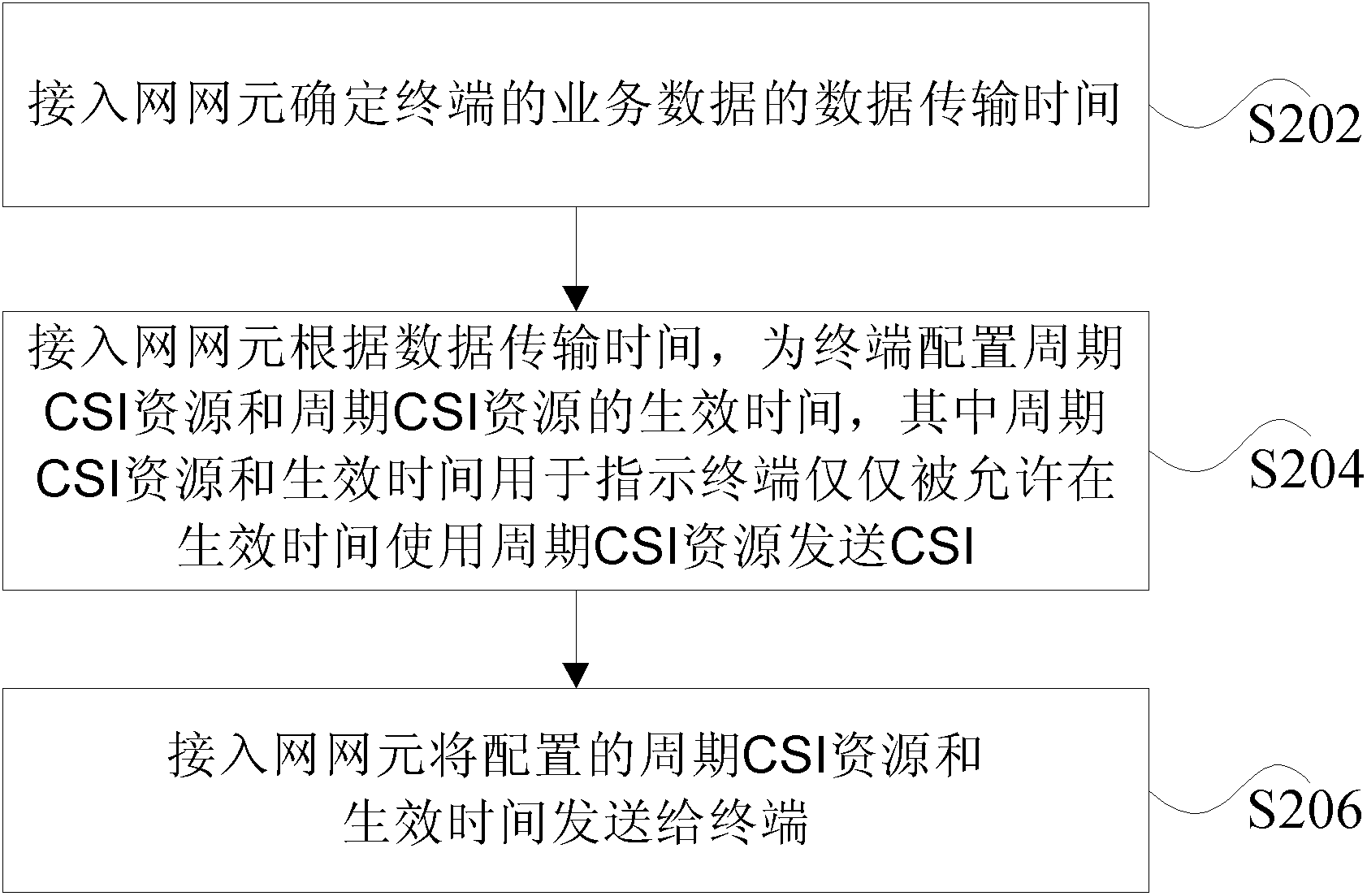
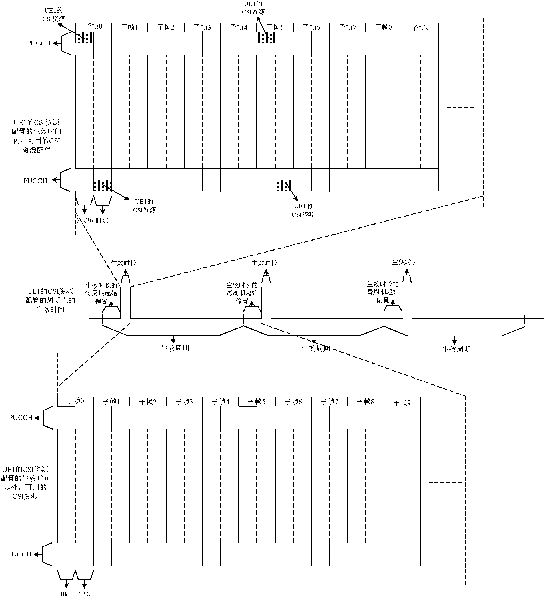
The invention discloses a reporting method and a reporting device for a wireless channel state indicator (CSI). The method comprises the following steps that: a network element of an access network determines the data transmission time of service data of a terminal; the network element of the access network configures periodical CSI resources and the effective time of the periodical CSI resources for the terminal according to the data transmission time, wherein the periodical CSI resources and the effective time are used for indicating that the terminal is only permitted to transmit the CSI by using the periodical CSI resources within the effective time; and the network element of the access network transmits the configured periodical CSI resources and the configured effective time to the terminal. The terminal can be ensured to transmit the CSI by using the periodical CSI resources within the effective time, so that influence on the throughput of the terminal is avoided, and the addition of signaling overhead is avoided. The periodical CSI resources can be ensured to be used by other terminals outside the effective time, so that the utilization efficiency of the CSI resources is improved.

Description

technical field [0001] The present invention relates to the communication field, in particular to a method and device for reporting wireless channel state information. Background technique [0002] At present, the wireless channel state information (Channel State Indicator, referred to as CSI) mechanism. The function of CSI is the user equipment (User Equipment, referred to as UE) feedback on downlink radio channel conditions, and the evolved Node B (EvolvedNodeB, referred to as eNB) assists radio resource scheduling according to the feedback, and realizes channel adaptation. [0003] The CSI includes: Channel Quality Indicator (CQI for short), Precoding Matrix Indicator (PMI for short), Recoding Type Indicator (PTI for short), Rank Indicator (Rank Indicator, referred to as RI). They are described respectively below. [0004] (1), CQI refers to the downlink channel quality measured by the UE. The UE maps the channel quality information into CQI, and then sends it to the ...

Claims


Application Information

Patent Timeline
Patent Type & Authority Applications(China)
IPC IPC(8): H04L1/06H04W24/10H04W72/12
CPCH04L1/0027H04L1/06H04L1/0026
Inventor 戴谦
Owner ZTE CORP
Learn More