Handle system for handheld power tool

A hand-held tool and handle technology, which is applied in the field of power-driven hand-held tools, can solve the problems of fastening parts detached from the tool and fastening parts loose, and achieve the effect of easy insertion

Active Publication Date: 2015-05-20
HUSQVARNA AB
View PDF4 Cites 0 Cited by
  • Summary
  • Abstract
  • Description
  • Claims
  • Application Information

AI Technical Summary

Problems solved by technology

Another problem with such systems is that when these systems are used with power tools such as hedge trimmers that generate a lot of vibration, after a period of operation the fastening parts may loosen and eventually the fastening parts may become dislodged from the tool

Method used


Image

  • Handle system for handheld power tool
  • Handle system for handheld power tool
  • Handle system for handheld power tool

Examples


Embodiment Construction

[0043] The present invention will be described more fully hereinafter with reference to the accompanying drawings, in which exemplary embodiments of the invention incorporating one or more aspects of the invention are shown. This invention may, however, be embodied in many different forms and should not be construed as limited to the embodiments set forth herein; rather, these embodiments are provided so that this disclosure will be thorough and complete, and inform the art The skilled artisan fully conveys the scope of the present invention. For example, one or more aspects of the invention can be used in other embodiments and even other types of devices. In the figures, the same reference numbers refer to the same elements.

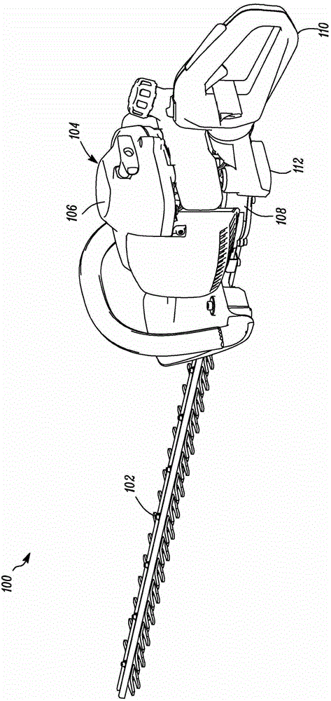
[0044] figure 1 A perspective view of a powered hand tool 100 according to one embodiment of the invention is shown. exist figure 1 In the exemplary embodiment shown, the powered hand tool 100 is a hedge trimmer. However, the invention may also be ...


PUM


Abstract

The present invention relates to a method and devices for mounting and securing a handle (110) on a power driven hand tool (100) The power driven hand tool (100) is provided with a main body (104) comprising a housing (106) with a drive unit for driving a working member of the tool (100), a handle (110) for user operation of the tool (100), and a connecting part (112) for connecting the handle (110) with the main body (106). Further, a front end of the handle (110) may be inserted into a rear end of the connecting part (112) in a first rotational position in relation to the connecting part (112), and the handle (110) may be rotated into a second rotational position in relation to the connecting part (112). In the second rotational position, the handle (110) and the connecting part (112) are locked to each other by means of an automatic locking mechanism.

Description

technical field [0001] The present invention relates to a power-operated hand tool comprising a removable handle, and the invention relates to such a handle itself. The invention also relates to a method for mounting and securing a handle to a power driven hand tool. Background technique [0002] Power-operated hand tools, such as, but not limited to, hedge trimmers, are sometimes provided with handles that are detachable from the body of the tool. In addition, the handle can be rotated relative to the tool for providing an ergonomic working position in various working environments. [0003] Typically, current systems for mounting detachable handles on power tools include some fastening components, such as screws or clips. These widgets can be easily lost. Also, the assembly process can be time consuming if several fastening components need to be placed during the assembly process. In addition, fastening members such as screws require the use of a screwdriver or the like...

Claims


Application Information

Patent Timeline
Patent Type & Authority Patents(China)
IPC IPC(8): A01G3/053B25F5/02B25G3/16
CPCA01G3/053Y10T29/49826Y10T29/49876B25F5/02
Inventor 卡尔-约翰·丰斯特凡·瓦尔弗里德松乌尔里克·耶耶尔瓦尔马蒂亚斯·奈巴克卡
Owner HUSQVARNA AB
Why Eureka
Try Eureka