compact generator

A generator, alternator technology, applied in the direction of engine components, machine/engine, engine cooling, etc., can solve the problem of incompatibility between compactness and acceptable noise level, and achieve the effect of longitudinal volume reduction

Active Publication Date: 2016-05-25
SDMO IND
View PDF5 Cites 0 Cited by
  • Summary
  • Abstract
  • Description
  • Claims
  • Application Information

AI Technical Summary

Problems solved by technology

[0013] Therefore, at present, there is an incompatibility between compactness and acceptable noise levels

Method used


Image

  • compact generator
  • compact generator
  • compact generator

Examples


Embodiment Construction

[0053] In the figures, for the sake of illustration and clarity, scale and scale have not been strictly adhered to.

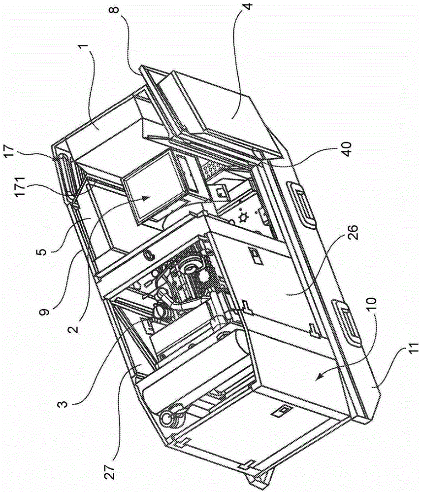
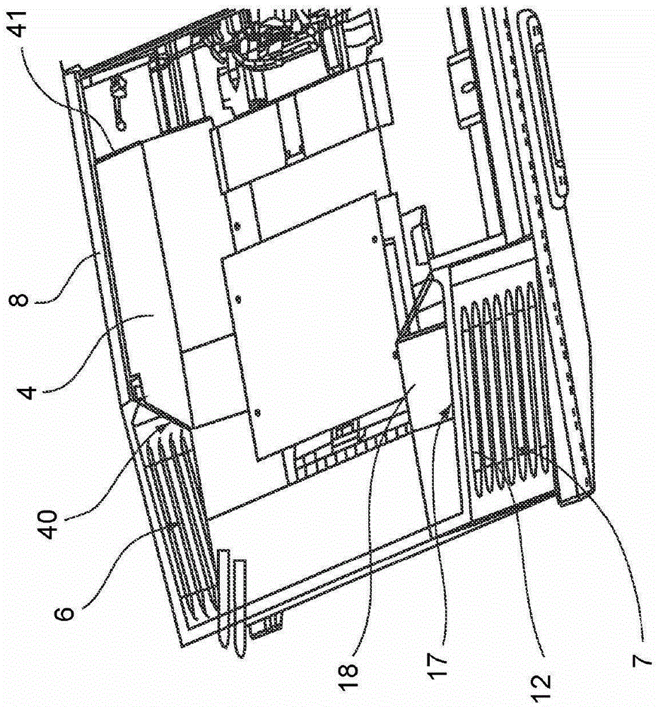
[0054] In the following detailed description with reference to the figures, unless otherwise indicated, each part of the generator is described as being arranged when the generator is placed on a planar horizontal support. This arrangement is especially figure 1 as well as figure 2 shown in .

[0055] Such as figure 1 As shown, the generator according to the invention comprises a cover 10 or casing extending in the longitudinal direction and mounted on a protruding frame 11 . The longitudinal direction is the main direction of the generator. According to the embodiment of the figures, the generator has a substantially parallelepiped shape and the longitudinal direction is the direction of extension of this parallelepiped, ie substantially parallel to the direction of the longitudinal walls of said parallelepiped forming the cover.

[0056]The generator ...


PUM


Abstract

The invention relates to an electricity generator set comprising a casing (10) extending in a longitudinal direction; a combustion engine (3) mounted on the casing (10); an alternator (2) mounted on the casing (10) and connected to the said combustion engine (3) in order to be able to convert the energy received from the combustion engine (3) into electrical energy; a control and connection housing (1) connected to said alternator; at least one air intake aperture (6; 7)allowing air into said casing (10), characterized in that it comprises at least one air diffuser (4; 5) mounted on a side wall of said casing (10) between an air inlet aperture (6; 7) and said combustion engine (3).

Description

technical field [0001] The invention relates to a generator comprising an engine, an alternator and a control unit. More specifically, the present invention relates to compact electric generators. Background technique [0002] A generator is an independent device that allows the generation of electrical energy from a heat engine. Thus, the generator makes it possible to overcome failures of the utility grid, or to supply electric power to electrical installations in areas where the utility grid is not available. [0003] As is well known, a generator consists of: [0004] -frame, [0005] - a heat engine mounted on the frame, [0006] - an alternator mounted on the frame and connected to the heat engine so as to be able to convert the energy received from the heat engine into electrical energy, [0007] - the control and connection unit connected to the alternator, [0008] - At least one air intake in the cover for supplying power to the heat engine. [0009] Air int...

Claims


Application Information

Patent Timeline
Patent Type & Authority Patents(China)
IPC IPC(8): F01P11/12F02B63/04F02B77/13
CPCF02B77/13F01P11/12F02B63/04F02B2063/045
Inventor 克劳德·阿斯科埃
Owner SDMO IND
Why Eureka
Try Eureka