Oil tank fixed to the engine block

A technology of engine body and oil tank, which is applied in the direction of engine lubrication, engine components, machine/engine, etc., can solve problems such as engine failure, and achieve the effect of reducing manufacturing costs

Active Publication Date: 2016-03-30
NOVARES FRANCE
View PDF5 Cites 0 Cited by
  • Summary
  • Abstract
  • Description
  • Claims
  • Application Information

AI Technical Summary

Problems solved by technology

The main disadvantage of this type of sump is that once a major shock is applied to the sump of the filter, the filter may become covered and prevent the circulation of the oil, causing the engine to fail

Method used


Image

  • Oil tank fixed to the engine block
  • Oil tank fixed to the engine block
  • Oil tank fixed to the engine block

Examples


Embodiment Construction

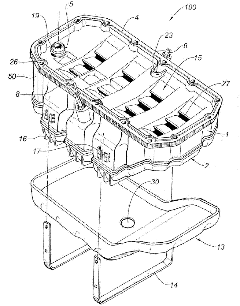
[0047] figure 1 The lower engine module or oil tank module 100 formed by the upper shell 1 and the lower shell 2 assembled together is shown without limitation. The oil tank 100 is designed to be fixed in the engine block 24 of an internal combustion engine, such as Image 6 Shown.

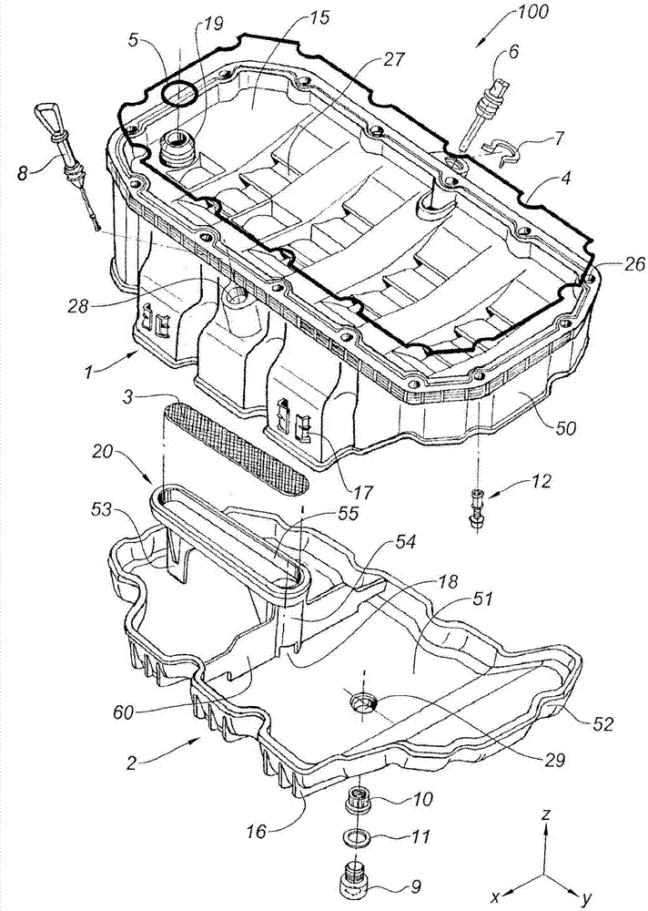
[0048] Such as figure 2 As shown, the axis Z is defined as a vertical axis, and the axis X and the axis Y define a horizontal plane. The terms "up", "down", "high", and "low" are used relative to the Z axis. The term "longitudinal" is used relative to axis Y, and the term "transverse" is used relative to axis X. The engine oil tank 100 is depicted in the figure in this case.

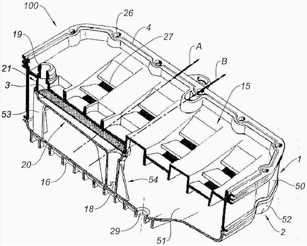
[0049] The upper shell 1 integrates multiple components to achieve normal operation of the device.

[0050] The upper shell 1 is molded as a single element. For example, it can be obtained by injecting plastic, molding a thermoplastic material, or molding aluminum. It includes an upper wall 15 forming an anti-emulsification p...


PUM


Abstract

The sump comprises: a lower shell (2) comprising an element that forms a lower portion (20) of a suction strainer, the lower shell and the said element being produced as a single piece by moulding or by casting; an upper shell (1) comprising an element forming an upper portion (21) of the suction strainer, and a wall forming an anti-emulsion plate (15), the upper shell, the said element and the anti-emulsion plate being produced as a single piece by moulding or by casting. The shells are assembled with one another in a fluid tight fashion to form a rigid casing, the lower portion and the upper portion of the suction strainer being, when the shells are assembled, assembled with one another with a grating (3) interposed between them so as to form a suction strainer that allows oil to be drawn up towards the engine.

Description

Technical field [0001] The invention relates to an oil tank for fixing on the engine block of an internal combustion engine. Background technique [0002] The main purpose of the oil tank is to collect oil for lubricating all rotating or translating mechanical parts (such as camshafts, valve stems, crankshaft bearings, piston / cylinder contact surfaces, piston / connecting rod contact surfaces, crankshaft / connecting rod contact surfaces, etc.) . The oil tank pushes the oil toward the multiple parts to be lubricated, and the oil then falls into the oil tank through at least one circuit (according to the situation, through natural flow or guided return). [0003] Generally, the oil tank includes a lower shell installed below the engine block. This type of oil tank contains a filter in its internal space, which makes it possible to prevent the solid matter contained in the oil so that it does not reach the suction opening of the pump; it also contains an anti-emulsification plate to pr...

Claims


Application Information

Patent Timeline
Patent Type & Authority Patents(China)
IPC IPC(8): F01M11/00
CPCF01M11/0004F01M2011/0012F01M2011/002F01M2011/0029F01M2011/0033F01M2011/005F01M2011/0066F01M2011/007F01M2011/0087F01M2011/0091
Inventor 伯努瓦·佩伦
Owner NOVARES FRANCE
Why Eureka
Try Eureka