
Pressure sensor

A pressure sensor and inductance coil technology, which is used in the measurement of fluid pressure, and the display of liquid level indicators and instruments through pressure measurement.

Inactive Publication Date: 2013-02-20
HANGZHOU KAMBAYASHI ELECTRONICS
View PDF8 Cites 9 Cited by
  • Summary
  • Abstract
  • Description
  • Claims
  • Application Information

AI Technical Summary

Problems solved by technology

[0004] The present invention aims to solve the problem that the output frequency deviation of the current inductive pressure sensor is large, which leads to the decrease of the sensor precision. Therefore, a pressure sensor of the present invention is provided, and the pressure sensor has high measurement accuracy.

Method used


Image

  • Pressure sensor
  • Pressure sensor
  • Pressure sensor

Examples


Embodiment 1

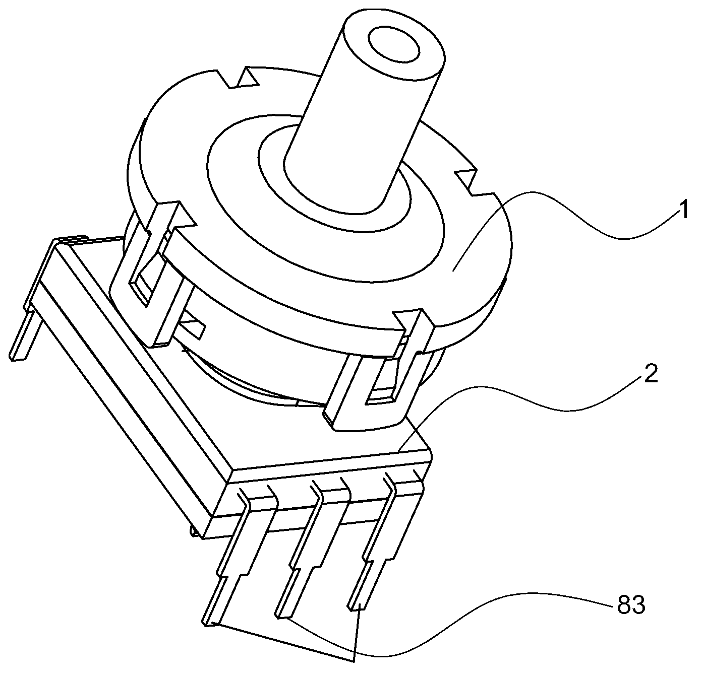
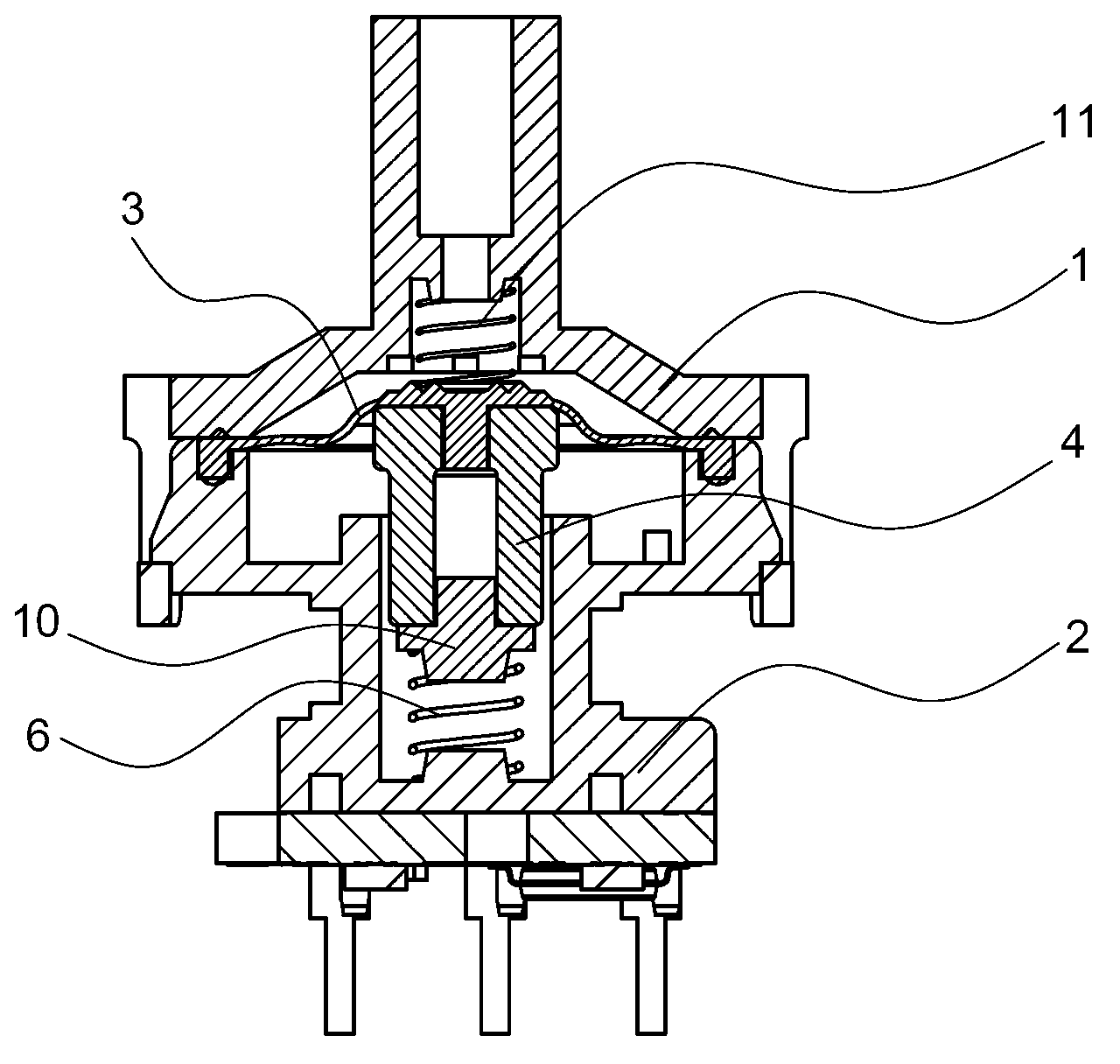
[0024] The pressure sensor of this embodiment includes a gas cover 1 and a housing 2. The housing has a skeleton around which coils are wound. An elastic diaphragm 3 is fixed at the junction of the elastic diaphragm, and an iron core 4 is embedded in the center of the elastic diaphragm. The iron core can move axially in the skeleton with the elastic diaphragm, and an inductor is wound on the skeleton of the housing. Coil 5, a spring 6 is installed between the lower end of the iron core and the bottom surface of the skeleton cavity of the housing, a circuit board 7 is connected under the housing, a memory device 71 is arranged on the circuit board, and a frequency signal output terminal is fixed on the housing 8 and the memory signal input and output terminal 9, one end 81 of the frequency signal output terminal and one end 91 of the memory signal input and output terminal output signals to the outside, the middle part 82 of the frequency information output terminal and the midd...

Embodiment 2

[0055] For the pressure sensor of this embodiment, see Figure 4 , Figure 7 , the elastic diaphragm is provided with a spring two 11 above, which can make the sensor start to record the curve when starting, and an iron core support 10 is housed between the iron core 4 and the spring one 6 . The other constructions are the same as in Embodiment 1.


PUM


Abstract

The invention provides a pressure sensor with a small measurement error. An elastic membrane (3) is fixedly arranged at a combined part of an air cover and a shell; an iron core (4) is arranged at the center of the elastic membrane; an inductance coil (5) is wound on a framework of the shell; a circuit board (7) is arranged below the shell; the circuit board is provided with a memory device (71); the shell is fixedly provided with a frequency signal output terminal (8) and a memory signal input / output terminal (9); one end (81) of the frequency signal output terminal and one end (91) of the memory signal input / output terminal outward output signals; a middle part (82) of the frequency signal output terminal and a middle part (92) of the memory signal input / output terminal are fixed with the shell; the other end (83) of the frequency signal output terminal and the other end (93) of the memory signal input / output terminal are connected with the circuit board; and the memory device stores a frequency value obtained by outputting through the frequency signal output terminal under different pressures. The pressure sensor disclosed by the invention is applicable to being used as a water level pressure sensor.

Description

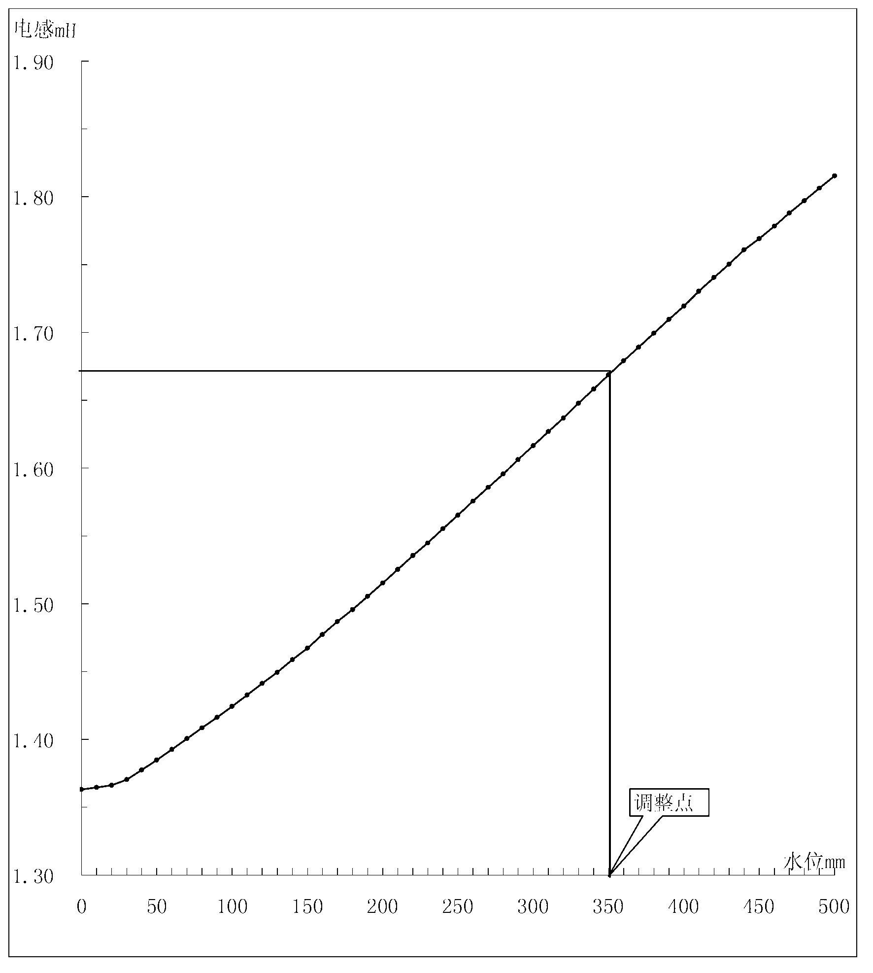
technical field [0001] The invention relates to a pressure sensor, in particular to a pressure sensor installed on washing machines, dishwashers and other household appliances for detecting the water level of the washing machines, dishwashers and other equipment when they are working. Background technique [0002] At present, the most widely used water level sensor for household appliances uses the following principle: water pressure is transmitted to the sensor air chamber through the air pipe to generate air pressure. When the core moves inside the coil, the inductance (L) of the coil changes approximately linearly with the displacement of the iron core, and the displacement of the iron core corresponds to the water level pressure. The displacement of the iron core is converted into the water level pressure, and the water level pressure and The relationship between the output inductance as figure 1 shown. [0003] The pressure sensor of Chinese invention patent ZL2008200...

Claims


Application Information

Patent Timeline
Patent Type & Authority Applications(China)
IPC IPC(8): G01L9/00G01F23/14
Inventor 鲍鹏飞邓睿王华
Owner HANGZHOU KAMBAYASHI ELECTRONICS
Learn More