Method and device for improving double-tunnel reliability

A reliability and tunnel technology, applied in data exchange, digital transmission system, electrical components, etc. through path configuration, can solve problems such as service interruption, unfavorable rational use of network bandwidth resources, unreachable video service traffic, etc., to alleviate traffic detour effect

Active Publication Date: 2013-02-20
ZHEJIANG UNIVIEW TECH CO LTD
View PDF6 Cites 6 Cited by
  • Summary
  • Abstract
  • Description
  • Claims
  • Application Information

AI Technical Summary

Problems solved by technology

[0006] However, in many actual networking applications, VM / DM / IPSAN may also need to use tunnels to establish connections. At this time, VM, IPSAN, and DM all need to establish connections with MS A and MS B. Such a networking solution is widely used in applications. there will be some problems
Please refer to figure 2 First of all, from the perspective of service flow, when VM selects MS for EC, it usually selects according to the load of MS. Suppose VM selects MS B for EC1, then the video service traffic is unreachable, or the traffic must go to MS first. A, forwarded by MS A to MS B, and then forwarded to the user terminal equipment. Obviously, in this case, traffic bypass will occur, which is not conducive to the rational use of network bandwidth resources.
Secondly, from the perspective of signaling flow, if the tunnel connection between VM and MS A is interrupted, the terminals connected to MS A will not be able to access the VM. Since VM also uses tunnel communication, other terminals do not know to bypass MS B. VM can only be accessed because it only knows that the next hop is MS A, so signaling traffic cannot bypass MS B with the assistance of MS A like business traffic. At this time, the signaling channels of many terminal devices will not be established. May cause widespread business disruption

Method used


Image

  • Method and device for improving double-tunnel reliability
  • Method and device for improving double-tunnel reliability
  • Method and device for improving double-tunnel reliability

Examples


Embodiment Construction

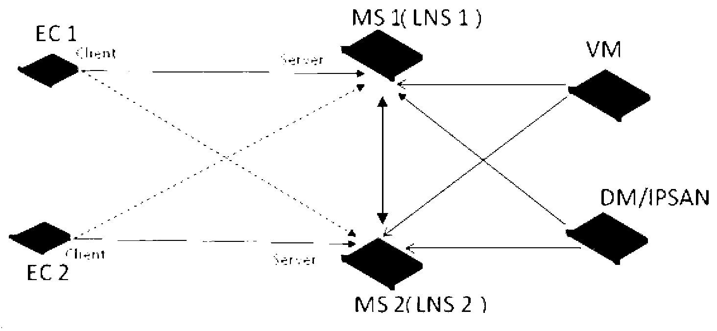
[0024] In one embodiment, the present invention provides a solution to solve the problems of traffic bypass and link backup in a double-tunnel relay network. Please refer to image 3 , in this embodiment, MS1 and MS2 are integrated with tunnel relay servers (LNS1 and LNS2), on which are respectively configured the IP addresses in the first address pool P1 and the second address pool P2, P1 and P2 as tunnel servers It is used as the inner layer IP address of the tunnel (also known as the tunnel IP address) for each monitoring terminal to use during tunnel communication, and the IP addresses in P1 and P2 do not overlap. In a preferred manner, the tunnel IP address of the monitoring terminal is usually dynamically allocated by the LNS.

[0025] The IP addresses of LNS1 and LNS2 are configured on the monitoring terminal (such as decoding terminal VC / XP or encoding terminal EC) as the destination IP address of L2TP relay dialing. In a preferred mode, each monitoring terminal sele...


PUM


Abstract

The invention provides a method for improving double-tunnel reliability. The method comprises the steps of establishing tunnel connection between a first L2TP network server (LNS) and a monitoring terminal and between the first LNS and a monitoring server respectively, and allocating a tunnel Internet protocol (IP) address in a first tunnel IP address pool to the monitoring terminal, wherein a tunnel IP address of the monitoring server is configured in advance, and the tunnel connection is established between the monitoring server and a second LNS; learning routing information of the monitoring terminal, which serves as a main routing to be added into a routing list, adding routing information issued by the second LNS into the routing list to serve as a spare routing; issuing the learnt routing information to the second LNS; and transmitting a message coming from the monitoring terminal or the monitoring server according to the routing list, and using the spare routing to transmit the message when the main routing fails. The method effectively solves the problem that part of terminal services are interrupted when the connection between video management (VM) and a media server (MS) in the prior art breaks down, and the method can solve the problem of flow circumambulating through cooperation of a plurality of devices.

Description

technical field [0001] The invention relates to the field of video monitoring, in particular to a method and device for improving the reliability of double tunnels in a video monitoring system. Background technique [0002] With the development of IP monitoring technology, IP monitoring can fully meet the needs of various small, medium and large monitoring networking. In various networking environments, the NAT networking introduced to solve the limitation of the number of IPv4 addresses is It is a common networking type. In order to solve various problems during NAT traversal, the applicant proposes a technical solution for tunnel traversal. For specific implementation, please refer to the relevant patent application filed by the applicant. In the tunnel traversal solution, the L2TP tunnel is a commonly used tunneling protocol. The specific application scenarios are as follows figure 1 shown. [0003] exist figure 1 In the scenario, the media transfer server (MS) inside ...

Claims


Application Information

Patent Timeline
Patent Type & Authority Applications(China)
IPC IPC(8): H04L12/707H04L12/741H04L12/46H04L45/24H04L45/74
Inventor 任俊峰周迪
Owner ZHEJIANG UNIVIEW TECH CO LTD
Why Eureka
Try Eureka