Cell switching method, device and system

A cell handover and connection reconfiguration technology, applied in the communication field, can solve problems such as service interruption, avoid service interruption and improve user experience

Inactive Publication Date: 2017-11-28
ZTE CORP
View PDF0 Cites 8 Cited by
  • Summary
  • Abstract
  • Description
  • Claims
  • Application Information

AI Technical Summary

Problems solved by technology

[0005] Embodiments of the present invention provide a cell handover method, device, and system to at least solve the problem of service interruption when a UE is handed over from a source base station to a target base station in the related art

Method used


Image

  • Cell switching method, device and system
  • Cell switching method, device and system
  • Cell switching method, device and system

Examples


Embodiment 1

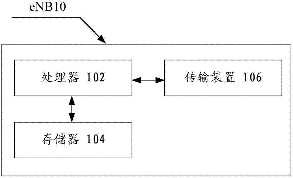
[0038] The method embodiment provided in Embodiment 1 of the present application may be executed in an eNB, a computer terminal, or a similar computing device. Taking running on the base station eNB as an example, figure 1 It is a block diagram of the hardware structure of the eNB applying the cell handover method according to the embodiment of the present invention. like figure 1 As shown, eNB10 may include one or more (only one is shown in the figure) processors 102 (processors 102 may include but not limited to processing devices such as microprocessor MCU or programmable logic device FPGA) for storing data memory 104, and transmission means 106 for communication functions. Those of ordinary skill in the art can understand that, figure 1 The shown structure is only for illustration, and it does not limit the structure of the above-mentioned electronic device. For example, eNB10 may also include figure 1 more or fewer components than shown in, or with figure 1 Differen...

Embodiment 2

[0062] This embodiment also provides a cell handover device and system, which are used to implement the above embodiments and preferred implementation modes, and those that have already been described will not be repeated. As used below, the term "module" may be a combination of software and / or hardware that realizes a predetermined function. Although the devices described in the following embodiments are preferably implemented in software, implementations in hardware, or a combination of software and hardware are also possible and contemplated.

[0063] Figure 4 is a structural block diagram of a cell handover device according to an embodiment of the present invention, which is applied in a source base station where a user equipment UE performs handover from a source base station to a target base station, such as Figure 4 As shown, the device includes:

[0064] The first sending module 40 is configured to send a radio resource control RRC connection reconfiguration messag...

Embodiment 3

[0074] This embodiment is an optional embodiment according to the present invention, and is used to describe the present invention in detail:

[0075] This embodiment provides an optimized switching method, including:

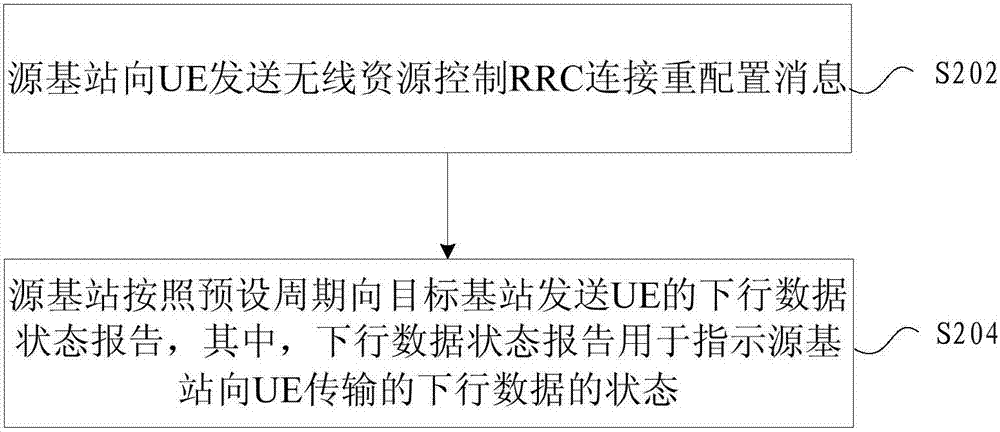
[0076] During the handover process of the UE from the source cell of the source eNB to the target cell of the target eNB, after the source cell sends the RRC Connection Reconfiguration message to the UE, the source eNB periodically sends the downlink data status report of the UE to the target eNB, and The downlink data forwarding (Data forwarding) of the UE is started to the target eNB.

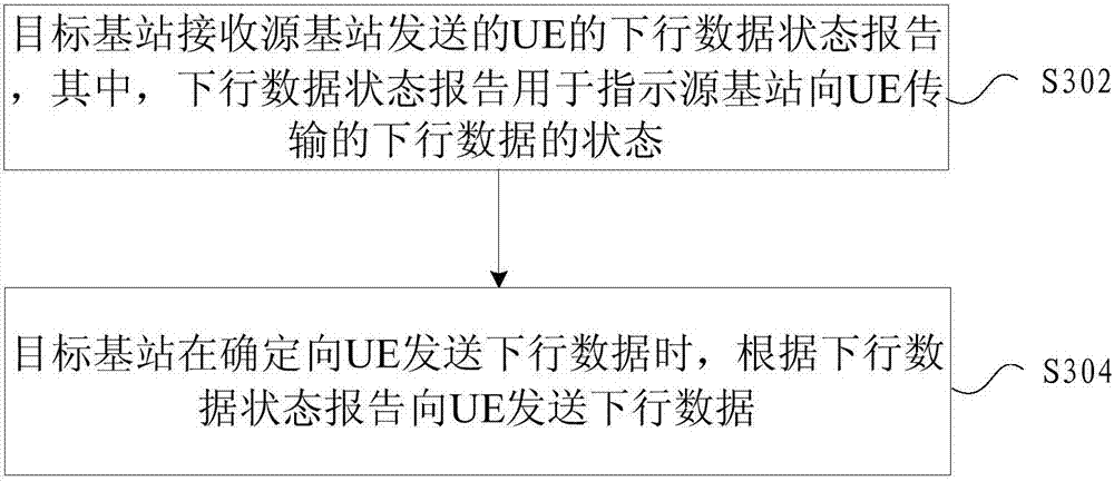
[0077] When the target eNB determines that the target cell can send downlink data to the UE, the target eNB starts to send downlink data to the UE according to the latest downlink data status report of the UE received from the source eNB, and sends the downlink data of the UE to the source eNB The notification of the status report stops, but the downlink data forwarding of th...


PUM


Abstract

The present invention provides a cell handover method, device and system, wherein the method is applied in the process of user equipment UE handover from a source base station to a target base station, including: the source base station sends a radio resource control RRC connection reconnection to the UE Configuration message; the source base station sends a downlink data status report of the UE to the target base station according to a preset period, where the downlink data status report is used to indicate the downlink data transmitted by the source base station to the UE Status Through the present invention, the problem of service interruption when the UE is handed over from the source base station to the target base station in the related art is solved.

Description

technical field [0001] The present invention relates to the communication field, in particular, to a cell switching method, device and system. Background technique [0002] A Long Term Evolution (LTE) network includes an Evolved Universal Terrestrial Radio Access Network (Evolved Universal Terrestrial Radio Access Network, E-UTRAN) and a Core Network (Core Network, CN). The E-UTRAN includes an evolved base station (evolved Node B, eNB). The CN includes a mobile management entity (Mobile Management Entity, MME) and a serving gateway (Serving Gateway, S-GW), etc. The eNB and CN are connected through the S1 interface, and the eNBs can be connected through the X2 interface. One eNB can manage one or more cells (Cell). An interface between a user equipment (User Equipment, UE) and a cell is called a Uu interface (or an air interface). [0003] In the LTE system of the related technology, during the handover process from one eNB cell to another eNB cell, the UE will first disc...

Claims


Application Information

Patent Timeline
Patent Type & Authority Applications(China)
IPC IPC(8): H04W36/00H04W36/18
CPCH04W36/0055H04W36/18
Inventor 方建民
Owner ZTE CORP
Why Eureka
Try Eureka