Method of forming gas-enriched fluid

a gas-enriched fluid and fluid technology, applied in the direction of catheters, other blood circulation devices, transportation and packaging, etc., can solve the problems of organ dysfunction or failure, complete organ failure, heart and brain progressively deterioration,

Inactive Publication Date: 2005-08-30
THEROX
View PDF87 Cites 31 Cited by
  • Summary
  • Abstract
  • Description
  • Claims
  • Application Information

AI Technical Summary

Benefits of technology

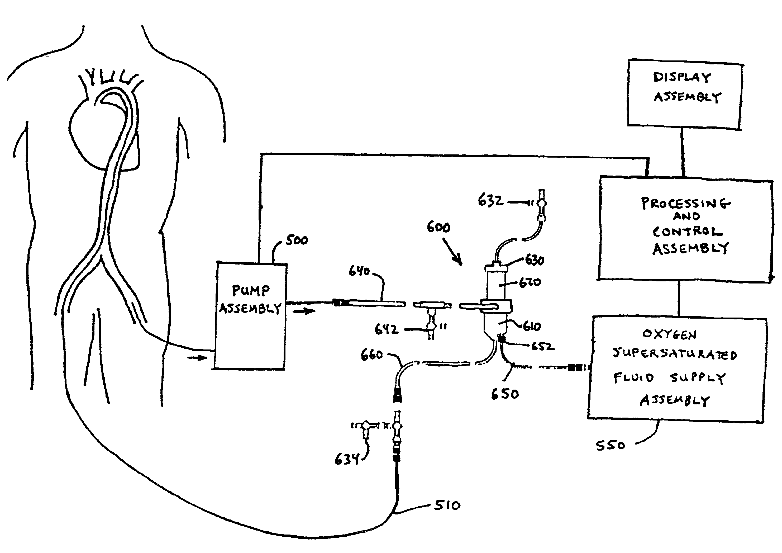
[0065]The system also may include various conventional items, such as sensors, flow meters (which also may serve a dual role as a macrobubble detector), or other clinical parameter monitoring devices; hydraulic components such as accumulators and valves for managing flow dynamics; access ports which permit withdrawal of fluids; filters or other safety devices to help ensure sterility; or other devices that generally may assist in controlling the flow of one or more of the fluids in the system. Advantageously, any such devices are positioned within the system and used so as to avoid causing the formation of clinically significant bubbles within the fluid flow paths, and / or to prevent fluid flow disruptions, e.g., blockages of capillaries or other fluid pathways. Further, the system advantageously comprises a biocompatible system acceptable for clinical use with human patients.

Problems solved by technology

Cell damage may result from oxygen deprivation for even brief periods of time, which may lead to organ dysfunction or failure.
For example, heart attack and stroke victims experience blood flow obstructions or diversions that prevent oxygen from being delivered to the cells of vital tissues.
Without oxygen, the heart and brain progressively deteriorate.
In severe cases death results from complete organ failure.
Less severe cases typically involve costly hospitalization, specialized treatments and lengthy rehabilitation.
In patients who suffer from acute myocardial infarction, if the myocardium is deprived of adequate levels of oxygenated blood for a prolonged period of time, irreversible damage to the heart can result.
Where the infarction is manifested in a heart attack, the coronary arteries fail to provide adequate blood flow to the heart muscle.
Even with the successful treatment of occluded vessels, a risk of tissue injury may still exist.
Reperfusion injury also may result, for example, due to slow coronary reflow or no reflow following angioplasty.
For some patients angioplasty procedures are not an attractive option for the treatment of vessel blockages.
Such patients typically are at increased risk of ischemia for reasons such as poor left ventricular function, lesion type and location, or the amount of the myocardium at risk.
Increased blood oxygen levels also may cause the normally perfused left ventricular cardiac tissue into hypercontractility to further increase blood flow through the treated coronary vessels.
There are drawbacks, however, to the use of a conventional oxygenator in an extracorporeal circuit for oxygenating blood.
Such systems typically are costly, complex and difficult to operate.
Such large priming volumes are undesirable for many reasons.
Further, conventional oxygenator systems are relatively difficult to turn on and off.
In addition, with extracorporeal circuits including conventional blood oxygenators there is a relatively high risk of inflammatory cell reaction and blood coagulation due to the relatively slow blood flow rates and the large blood contact surface area.
Perhaps one of the greatest disadvantages to using conventional blood oxygenation systems is that the maximum partial pressure of oxygen (pO2) that can be imparted to blood with commercially available oxygenators is about 500 mm Hg.
Thus, blood pO2 levels near or above 760 mm Hg cannot be achieved with conventional oxygenators.
However, use of hyperbaric oxygen therapy following restoration of coronary artery patency in the setting of an acute myocardial infarction is not practical.
Monitoring critically ill patients in a hyperbaric oxygen chamber is difficult.
Ear damage may occur.
Further, treatment times longer than 90 minutes cannot be provided without concern for pulmonary oxygen toxicity.

Method used


Image

  • Method of forming gas-enriched fluid
  • Method of forming gas-enriched fluid
  • Method of forming gas-enriched fluid

Examples


Embodiment Construction

[0094]The description below illustrates embodiments of the present invention. For the sake of clarity, not all features of an actual implementation of the present invention are described in this specification. It should be appreciated that in connection with developing any actual embodiment of the present invention many application-specific decisions must be made to achieve specific goals, which may vary from one application to another. Further, it should be appreciated that any such development effort might be complex and time-consuming, but would still be routine for those of ordinary skill in the art having the benefit of this disclosure.

[0095]For the sake of clarity and convenience, the various embodiments are described herein in the context of interventional cardiovascular applications generally involving acute or transient ischemia or post-ischemic tissues. However, the present invention may also be useful in other medical applications, such as cancer therapy (e.g., the delive...


PUM

PropertyMeasurementUnit
pressureaaaaaaaaaa
pressureaaaaaaaaaa
velocityaaaaaaaaaa

Abstract

A method for forming a gas-enriched fluid is provided. The method includes a step of providing a mixing chamber having a first inlet, a second inlet, and an outlet. A first fluid is delivered into the mixing chamber via the first inlet and flows vertically. A second fluid having a liquid phase supersaturated with a gas is delivered to the mixing chamber via the second inlet to mix with the first fluid and from the gas-enriched fluid.

Description

RELATED APPLICATIONS[0001]This application is a continuation of U.S. patent application Ser. No. 09 / 410,344 filed Sep. 30, 1999, which is incorporated herein by reference. This application is also a continuation-in-part of U.S. patent application Ser. No. 09 / 122,143 filed Jul. 24, 1998, now U.S. Pat. No. 6,180,059B 1, which is incorporated herein by reference.FIELD OF THE INVENTION[0002]The present invention relates generally to a system and method for oxygenating blood, and more particularly, to a system and method for providing oxygenated blood, e.g., hyperoxemic or hyperbaric blood, to a patient.BACKGROUND OF THE INVENTION[0003]Oxygen is a crucial nutrient for human cells. Cell damage may result from oxygen deprivation for even brief periods of time, which may lead to organ dysfunction or failure. For example, heart attack and stroke victims experience blood flow obstructions or diversions that prevent oxygen from being delivered to the cells of vital tissues. Without oxygen, the...

Claims


Application Information

Patent Timeline
Patent Type & Authority Patents(United States)
IPC IPC(8): A61M1/16A61M25/00A61M1/36
CPCA61M1/1698A61M1/3621A61M1/3626A61M25/0029C01B13/02B01F3/04758A61M1/3603A61M1/361A61M1/3612A61M1/3613A61M1/1678A61M1/32A61M25/0028A61M2025/0031A61M2025/0036A61M2025/0037A61M2025/004A61M2202/0476A61M2202/0007Y10S261/28B01F23/23413A61M1/3623
Inventor DIVINO, JR., VINCENTPATTERSON, WILLIAM R.CREECH, JEFFREY L.MYRICK, STEPHEN E.
Owner THEROX
Why Eureka
Try Eureka