Lock pin device

A lock pin and lock pin cover technology, applied in the manufacture of tools, hand-held tools, etc., can solve the problems of complex connection and release of parts, and achieve the effect of no sticking, flexible operation and reliable work

Inactive Publication Date: 2013-02-27
中国船舶重工集团公司第七〇五研究所
View PDF12 Cites 3 Cited by
  • Summary
  • Abstract
  • Description
  • Claims
  • Application Information

AI Technical Summary

Problems solved by technology

The existing connection methods between parts often use fixed connection methods such as screws, pins, and keys. The connection and release between parts are relatively complicated, and it is often necessary to disassemble the parts as a whole before performing the corresponding connection or release operation.

Method used


Image

  • Lock pin device
  • Lock pin device
  • Lock pin device

Examples


Embodiment Construction

[0022] Describe the present invention below in conjunction with specific embodiment:

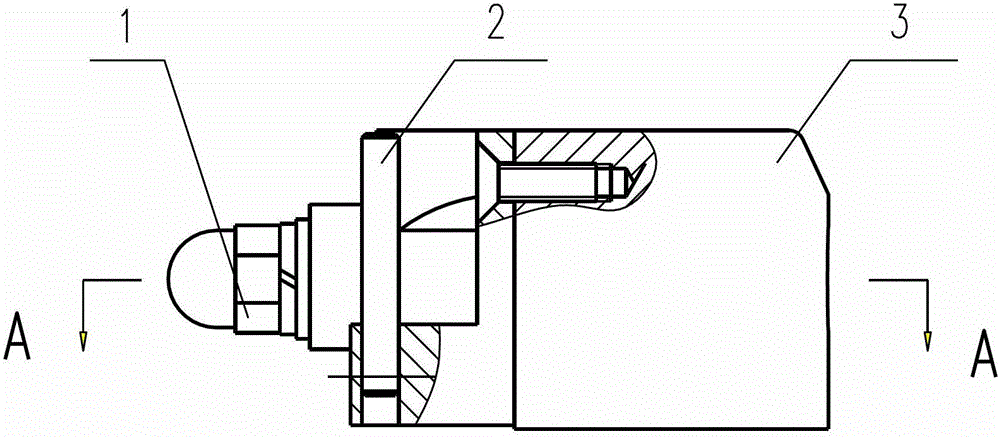
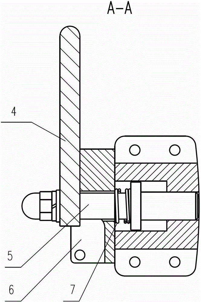
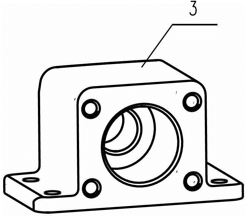
[0023] Refer to attached figure 1 And attached figure 2 , The locking device in this embodiment includes a locking base 3 , a locking handle 4 , a locking cover 6 and a locking pin 5 .

[0024] Refer to attached Figure 5 , the lock pin has a square shaft section near one end, the outer side of the square shaft section is a round thread section, and the middle part of the lock pin has a circular protrusion. Refer to attached Figure 4 , there is a square hole at the end of the handle of the lock pin, the square hole is matched with the square shaft section of the lock pin, and the lock pin handle and the lock pin are fixed by a round nut 1 on the outside of the square shaft section of the lock pin , so that the lock pin 5 can move together with the lock pin handle 4. Here, the square shaft section of the lock pin can be square or hexagonal, etc., and the square hole of the lock pin han...


PUM


Abstract

The invention discloses a lock pin device. The device comprises a lock pin base, a lock pin handle, a lock pin cover and a lock pin, wherein the lock pin device is fixed on one part to be connected by a screw through a fixing hole on the lock pin base, and the position on the other part to be connected, which corresponds to the lock pin, is provided with a lock pin hole. When the two parts are connected, the lock pin handle is rotated, the lock pin extends out to extend into the lock pin hole on the other part, and the connection between the two parts is achieved; in the state, the lock pin handle is attached to an A surface, the lock pin handle is limited between a plane on the lock pin cover and a positioning pin, and the reliable connection between the two parts is guaranteed. When the two parts are separated, the lock pin handle is rotated, the lock pin handle is lifted to the position of the lock pin surface groove D surface along a spiral surface, the lock pin is retracted, the two connected parts are separated, by means of the pressure action of a spring on a protrusion in the middle of the lock pin, the lock pin handle is attached to the groove, at the situation, the spring is in a pressing state, so that the lock pin can not run out to an extending direction, and the two parts can be reliably separated.

Description

technical field [0001] The invention relates to a lock pin device, which can conveniently carry out the connection and release operations between two parts. Background technique [0002] The locking pin device is used for connection and release between two parts. The existing connection methods between parts often adopt fixed connection methods such as screws, pins, and keys. The connection and release between parts are relatively complicated, and it is often necessary to disassemble the parts as a whole before performing the corresponding connection or release operation. Contents of the invention [0003] technical problem to be solved [0004] In order to solve the problems existing in the prior art, the present invention proposes a lock pin device, through the rotation of the handle, the lock pin is advanced or retreated along its axial direction, so as to realize the connection and release between the two parts, and the All have limited position design, flexible oper...

Claims


Application Information

Patent Timeline
IPC IPC(8): B25B27/00
Inventor 邵卫高卓孙铁绳汤伟江赵雄辉
Owner 中国船舶重工集团公司第七〇五研究所
Why Eureka
Try Eureka