
Connection structure for rotor spindle and crank shaft of double-end motor

A double-headed motor and connection structure technology, applied to rigid shaft couplings, couplings, mechanical equipment, etc., can solve problems such as machine damage, poor rotor shaft center balance, and large positioning errors

Inactive Publication Date: 2013-02-27
温岭市精仁机械有限公司
View PDF5 Cites 5 Cited by
  • Summary
  • Abstract
  • Description
  • Claims
  • Application Information

AI Technical Summary

Problems solved by technology

[0002] The rotor shaft of the motor rotates in the circumferential direction to generate driving torque, which drives the attached parts to move. It is widely used in the field of mechanical transmission. In order to use the power on both sides of the motor to achieve the effect of saving energy and reducing consumption, the The crankshaft is installed on the crankshaft, and the components to be driven are connected to the crankshaft. The existing connection structure between the crankshaft and the rotor shaft is: mill a plane on the rotor shaft, and lock the crankshaft eccentrically on the rotor shaft with a screw. The large positioning error in the angle of the rotor shaft leads to poor balance of the center of the rotor shaft, and the lack of locking force between the crankshaft and the rotor shaft, the crankshaft is easy to loose during rotation, and the balance of the crankshaft on both sides of the rotor shaft is poor, which affects the movement of the attached parts track, causing damage to the entire machine

Method used


Image

  • Connection structure for rotor spindle and crank shaft of double-end motor
  • Connection structure for rotor spindle and crank shaft of double-end motor
  • Connection structure for rotor spindle and crank shaft of double-end motor

Examples


Embodiment Construction

[0016] The following will clearly and completely describe the technical solutions in the embodiments of the present invention with reference to the accompanying drawings in the embodiments of the present invention. Obviously, the described embodiments are only some, not all, embodiments of the present invention. Based on the embodiments of the present invention, all other embodiments obtained by persons of ordinary skill in the art without creative efforts fall within the protection scope of the present invention.

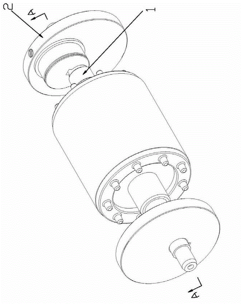
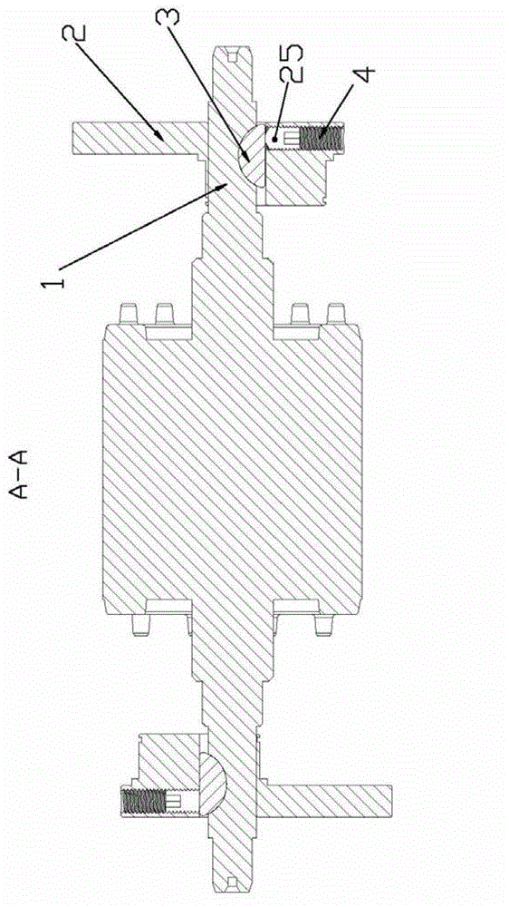
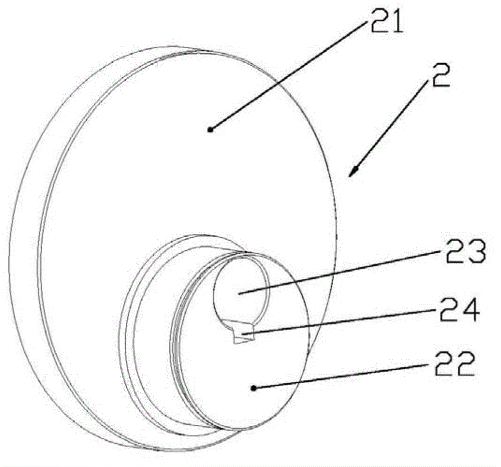
[0017] Such as figure 1 — Figure 5 As shown, the present invention discloses a connection structure between the rotor shaft and the crankshaft of a double-headed motor, including the rotor shaft 1 and the crankshaft 2, and the crankshaft 2 includes a cylindrical connecting seat 21 and a cylindrical transmission part 22. The transmission part 22 is located on one side of the bottom surface of the connection seat 21, forming an eccentric structure, and the transmis...


PUM


Abstract

The invention discloses a connection structure for a rotor spindle and a crank shaft of a double-end motor. The connection structure comprises the rotor spindle and the crank shaft, wherein the crank shaft comprises a cylinder connection base and a cylinder transmission part, the transmission part is located on one side of the bottom surface of the connection base to form an eccentric structure, the transmission part is provided with a rotor spindle installation hole which penetrates through the connection base, the crank shaft is provided with a clamp slot which is communicated with the rotor spindle installation hole, an installation slot is arranged on the rotor spindle corresponding to the clamp slot, a locating block is arranged in the installation slot and is adaptive to the clamp slot, and the crank shaft is provided with a drive mechanism for driving the locating block to swing. The connection structure is characterized in that the locating block and the drive mechanism for driving the locating block to swing are arranged between the rotor spindle and the crankshaft, so that when the locating block swings, the crank shaft is locked, as a result, the location of the crank shaft is guaranteed, the locking force between the crank shaft and the rotor spindle is increased, the crank shaft is prevented from being loosened in the rotation process, and the improvement of the center balance of the rotor spindle is guaranteed when both ends of the rotor spindle are provided with crankshafts.

Description

technical field [0001] The invention relates to the field of motors, in particular to a connection structure between a rotor shaft and a crankshaft of a double-head motor. Background technique [0002] The rotor shaft of the motor rotates in the circumferential direction to generate driving torque, which drives the attached parts to move. It is widely used in the field of mechanical transmission. The crankshaft is installed on the crankshaft, and the driven components are connected to the crankshaft. The existing connection structure between the crankshaft and the rotor shaft is as follows: a plane is milled on the rotor shaft, and the crankshaft is eccentrically locked on the rotor shaft with a screw. The large positioning error in the angle of the rotor shaft leads to poor balance of the center of the rotor shaft, and the lack of locking force between the crankshaft and the rotor shaft, the crankshaft is easy to loose during rotation, and the balance of the crankshaft on b...

Claims


Application Information

Patent Timeline
Patent Type & Authority Applications(China)
IPC IPC(8): F16D1/02
Inventor 吴成华
Owner 温岭市精仁机械有限公司
Learn More