Effect device for forming stage-lighting effects

A stage lighting and effect wheel technology, which is applied in the field of stage lighting, can solve the problems of pattern wheel shaking, slow movement, and increased manufacturing costs, and achieve the effects of increased change speed, sufficient range of motion, and reduced manufacturing costs

Active Publication Date: 2015-04-22
GUANGZHOU FINEART LIGHTING
View PDF3 Cites 0 Cited by
  • Summary
  • Abstract
  • Description
  • Claims
  • Application Information

AI Technical Summary

Problems solved by technology

In the existing field of stage lighting technology, the above-mentioned dynamic effect is usually achieved by placing a rotatable gobo wheel (i.e. effect wheel) in front of the light bulb of the stage lamp, but the effect of this gobo wheel is often relatively static, only The dynamic effect can only be produced when the gobo rotates around its own axis, so the effect produced by this structure is not yet satisfactory
[0003] In order to overcome the above defects, there is also a structure in the prior art that can produce a variety of dynamic effects, that is, a linear guide rail moving device is added on the basis of the original gobo wheel assembly, and the gobo wheel can be moved linearly, although this structure The above-mentioned defects can be overcome, but the following defects still exist: (1) Since the linear guide rail moving device needs to move the gobo wheel into or out of the light-transmitting hole, the linear guide rail moving device usually needs to be designed with a longer length and takes up more space. This will increase the overall structure of the stage lamp at the same time, which not only increases the manufacturing cost, but also makes the whole lamp appear cumbersome and inconvenient for transportation or storage; (2) Since the linear guide rail moving device takes up a large space, so , the internal structure of the lamp is usually relatively compact, and the internal parts are easy to collide with each other during operation, which will make the parts of the lamp easy to be damaged; (3) when this structure moves the gobo wheel linearly, the movement is usually relatively small. Slow, the movement of the gobo wheel is not flexible, and the lighting effect achieved is not ideal; (4) Since the linear guide rail moving device usually occupies a large span and the moving distance is long, and the area of ​​the gobo wheel is usually large, therefore, when driving the gobo wheel to move During the process, it is easy to cause the gobo wheel to shake, and this structure usually does not run smoothly, is not smooth, and is prone to jamming, deformation, etc., which makes the obtained lighting effect unsightly, and even makes the expected lighting effect flawed Or can not get the expected lighting effect

Method used


Image

  • Effect device for forming stage-lighting effects
  • Effect device for forming stage-lighting effects
  • Effect device for forming stage-lighting effects

Examples


Embodiment 1

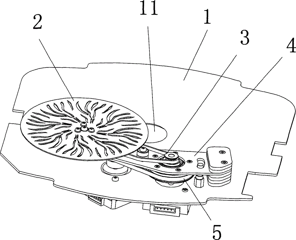
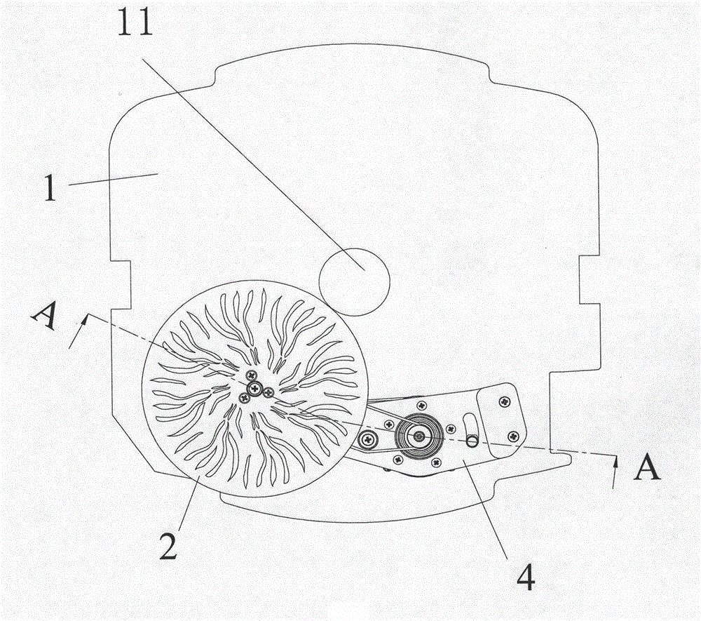
[0039] refer to figure 1 , the effect device used to shape the stage lighting effect includes:

[0040] A total support 1, the total support 1 is provided with a light-transmitting hole 11 for the passage of light beams;

[0041] The effect wheel 2, the effect wheel 2 can be a pattern wheel with irregular pattern holes, it can also be a color filter, a frosted glass sheet, a prism or any optical effect element, or a combination of the above elements;

[0042] Rotating mechanism 3, used to make the effect wheel 2 rotate around the axis of the effect wheel 2;

[0043] The moving mechanism is used to move the effect wheel 2 relative to the light transmission hole 11, so that the effect wheel 2 overlaps with the light transmission hole 11 or does not overlap with the light transmission hole 11, thereby producing different lighting effects.

[0044] refer to figure 1 Or 2, moving mechanism comprises rocking arm 4 and moving driving mechanism 5, and moving driving mechanism 5 com...

Embodiment 2

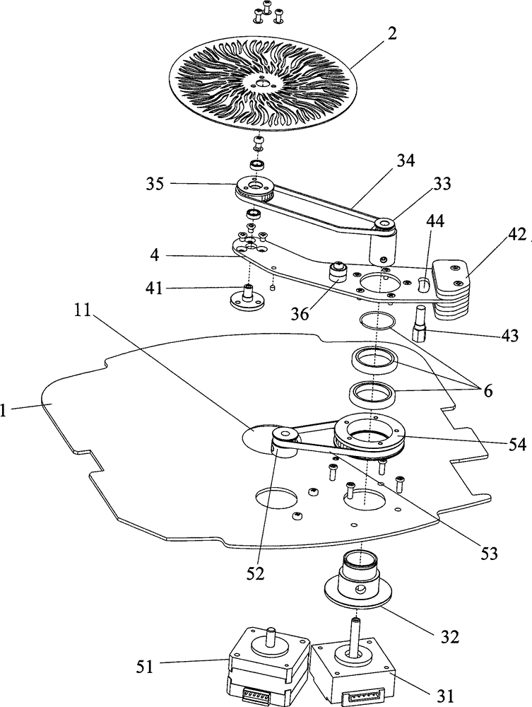
[0054] The effect devices used to shape the stage lighting effects include:

[0055] A total support 1, the total support 1 is provided with a light-transmitting hole 11 for the passage of light beams;

[0056] The effect wheel 2, the effect wheel 2 can be a pattern wheel with irregular pattern holes, it can also be a color filter, a frosted glass sheet, a prism or any optical effect element, or a combination of the above elements;

[0057] Rotating mechanism 3, used to make the effect wheel 2 rotate around the axis of the effect wheel 2;

[0058] The moving mechanism is used to move the effect wheel 2 to a position overlapping with the light-transmitting hole 11 or a position not overlapping with the light-transmitting hole 11 , so as to produce different lighting effects.

[0059] The moving mechanism includes a rocking arm 4 and a moving driving mechanism 5 , the moving driving mechanism 5 is a moving driving motor, and the output shaft of the driving motor is fixedly conn...


PUM


Abstract

The invention discloses an effect device for forming stage-lighting effects. The effect device comprises a main support, an effect wheel, a rotating mechanism and a moving mechanism, a light hole is arranged on the main support, the rotating mechanism is connected with the effect wheel and drives the effect wheel to rotate, the moving mechanism is used for enabling the effect wheel to move relative to the light hole, is mounted on the main support and comprises a rocker arm and a moving driving mechanism, the moving driving mechanism is connected with the rocker arm and drives the rocker arm to rotate, and the effect wheel is connected with the rocker arm. Relative movement of the effect wheel and the light hole is controlled by the rocker arm, the effect wheel can synchronously move with a moving motor, the change of pattern effects is greatly accelerated, the lighting effects are better, and the size of a lamp can be reduced.

Description

technical field [0001] The invention relates to the technical field of stage lighting, in particular to an effect device for shaping stage lighting effects. Background technique [0002] In the production of many TV and stage programs nowadays, it is not difficult to see that lighting engineers use different lighting effects to add a more lively atmosphere to the program, and usually require some unique pattern effects, such as flowing water, flames, floating white clouds and other effects. In the existing field of stage lighting technology, the above-mentioned dynamic effect is usually achieved by placing a rotatable gobo wheel (i.e. effect wheel) in front of the light bulb of the stage lamp, but the effect of this gobo wheel is often relatively static, only The dynamic effect can only be produced when the gobo wheel rotates around its own axis, therefore, the effect produced by this structure cannot meet the demand. [0003] In order to overcome the above defects, there i...

Claims


Application Information

Patent Timeline
Patent Type & Authority Patents(China)
IPC IPC(8): F21V14/08F21W131/105F21W131/406
Inventor 刘敏刘建华
Owner GUANGZHOU FINEART LIGHTING
Why Eureka
Try Eureka