Rotary encoder

A technology of rotary encoders and rotary code discs, applied in the field of rotary encoders, can solve problems such as complex structure, increased cost, and interference of rotary encoders, and achieve the effects of improving the purity of light received, improving precision, and improving phase characteristics

Active Publication Date: 2015-11-25
OMRON SHANGHAI
View PDF5 Cites 0 Cited by
  • Summary
  • Abstract
  • Description
  • Claims
  • Application Information

AI Technical Summary

Problems solved by technology

However, the light emitted after passing through this lens still cannot become an ideal parallel light, so there is still the influence of interfering light
Moreover, due to the addition of such a lens, the structure of the entire rotary encoder is complicated and the cost increases

Method used


Image

  • Rotary encoder
  • Rotary encoder
  • Rotary encoder

Examples


Embodiment Construction

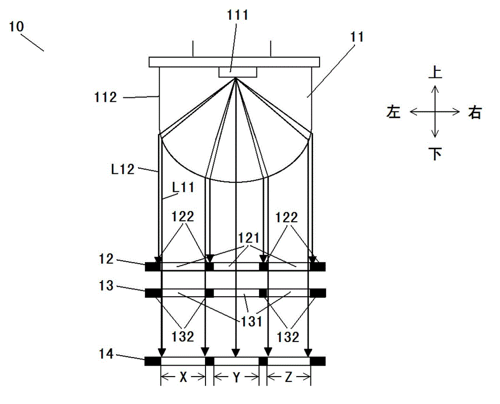
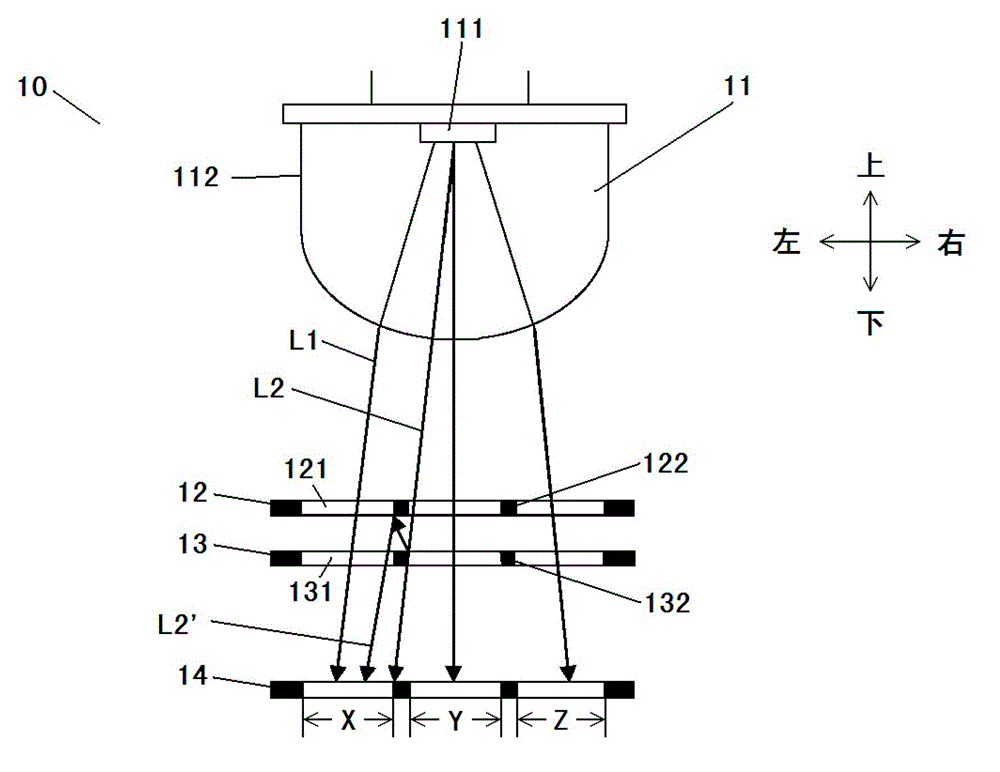
[0024] Embodiments of the present invention will be described in detail below in conjunction with the accompanying drawings. In the following description, the radial direction is the left-right direction in the figure, and the direction perpendicular to the disk surfaces of the first code wheel and the second code wheel is the up-down direction. In addition, the light rays shown in the drawings are only for illustrative purposes, and the present invention is not limited thereto, and the rest of the light rays are omitted for clarity of the drawings.

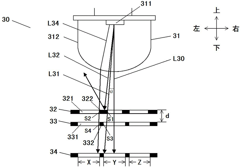
[0025] image 3 is a sectional view of the rotary encoder along the radial direction of the code disc according to the embodiment of the present invention. Such as image 3 As shown, the rotary encoder 30 includes a light source 31 , a first code wheel 32 , a second code wheel 33 and a light receiving surface 34 . The first code wheel 32 is a rotary code wheel rotatable with respect to its axis and the second code wheel 33 is ...


PUM


Abstract

The invention provides a rotary encoder which comprises a light source, a first code disc, and a second code disc, wherein the first code disc is provided with a plurality of first light transmitting parts and a plurality of first light shielding parts which are alternatively arranged along the radial direction of the first code disc; the second code disc is provided with a plurality of second light transmitting parts and a plurality of second light shielding parts which are alternatively arranged along the radial direction of the second code disc; the first code disc and the second code disc share one same axis; the first code disc is positioned between the light source and the second code disc; and in the direction perpendicular to the disc plane of the first code disc and in the direction perpendicular to the disc plane of the second disc, the plurality of first light transmitting parts and the plurality of second light transmitting parts are respectively in correspondence in sequence, the plurality of first light shielding parts and the plurality of second light shielding parts are respectively in correspondence in sequence, and the radial width of any one first light shielding part is larger than the radial width of the second light shielding part corresponding to the first light shielding part.

Description

technical field [0001] The invention relates to a rotary encoder, in particular to a code wheel in the rotary encoder. Background technique [0002] A rotary encoder is a sensor that converts the amount of mechanical displacement of rotation into an electrical signal, processes the signal, and detects position, speed, etc. It is mainly used for high-precision displacement and angle measurement in industrial automation, and has a wide range of applications. The requirements for the characteristics and precision of rotary encoders are also getting higher and higher. [0003] figure 1 It is a cross-sectional view of the rotary encoder along the radial direction of the code disc. In the rotary encoder 10, it includes a light source 11, a rotary code disc 12, a fixed code disc 13 and a light receiving surface 14 in sequence. The light source 11 is, for example, an LED lamp, including a light-emitting chip 111 and lens 112. Wherein, the rotary code wheel 12 has along the radia...

Claims


Application Information

Patent Timeline
Patent Type & Authority Patents(China)
IPC IPC(8): G01D5/32
Inventor 陈伟
Owner OMRON SHANGHAI
Why Eureka
Try Eureka