Balance force type electromagnetic relay clamping device with adjustable parameters

An electromagnetic relay and clamping device technology, which is applied to the measurement device shell, circuit breaker test and other directions, can solve the problems of unbalanced force type electromagnetic relay design parameter adjustment and other problems, and achieve the effect of quantitative research.

Inactive Publication Date: 2013-02-27
HARBIN INST OF TECH
View PDF4 Cites 4 Cited by
  • Summary
  • Abstract
  • Description
  • Claims
  • Application Information

AI Technical Summary

Problems solved by technology

[0008] The purpose of the present invention is to solve the problem that the design parameters of the balanced force electromagnetic relay cannot be adjusted in the existing various relay life measurement and experimental devices
The present invention designs a parameter-adjustable balance force electromagnetic relay clamping device capable of adjusting parameters for the existing balance force electromagnetic relay

Method used


Image

  • Balance force type electromagnetic relay clamping device with adjustable parameters
  • Balance force type electromagnetic relay clamping device with adjustable parameters
  • Balance force type electromagnetic relay clamping device with adjustable parameters

Examples


specific Embodiment approach 1

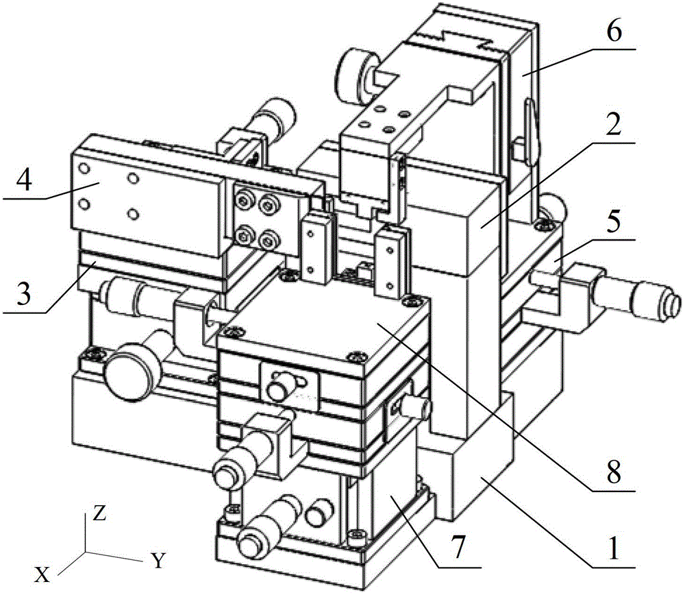
[0037] Specific implementation mode one, see figure 1 This embodiment will be described. The parameter-adjustable balance force electromagnetic relay clamping device described in this embodiment is composed of a base 1, an electromagnetic component positioning device 2, a short yoke adjusting device 3, a short yoke clamping device 4, an armature adjusting device 5, and an armature clamping device. Device 6, bottom plate adjustment device 7, bottom plate clamping device 8;

[0038] The electromagnetic component positioning device 2, the short yoke adjusting device 3, the armature adjusting device 5 and the bottom plate adjusting device 7 are fixed on the upper surface of the base 1; among them, the short yoke adjusting device 3 is used to support and fix the short yoke clip The clamping device 4 is used to adjust the position of the short yoke clamping device 4 in the X-Y two-dimensional plane; the short yoke clamping device 4 is used to cooperate with the electromagnetic comp...

specific Embodiment approach 2

[0041] Specific implementation mode two, see figure 2 with 3 This embodiment will be described. This embodiment is a further limitation on the structure of the parameter-adjustable balance force electromagnetic relay clamping device described in the first specific embodiment. In this embodiment,

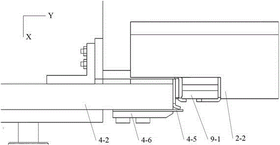
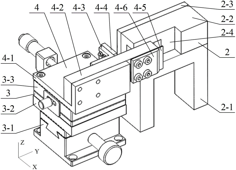
[0042] The electromagnetic component positioning device 2 is composed of a bracket 2-1, a positioning plate 2-2, and a side plate 2-3; -3 is fixedly installed on the upper end surface of the bracket 2-1, and the positioning plate 2-2 is provided with a positioning slot 2-4 for the electromagnetic component;

[0043] The short yoke adjustment device 3 is composed of a Y-axis adjustment slider 3-1, a connecting plate 3-2, and an X-axis adjustment slider 3-3; Fixed connection, the connecting plate 3-2 is fixed on the upper end surface of the Y-axis adjustment slider 3-1, and the X-axis adjustment slider 3-3 is fixed on the upper end surface of the connecting plate 3-2;

[0044] The...

specific Embodiment approach 3

[0046] Specific implementation mode three, see Figure 4 This embodiment will be described. This embodiment is a further limitation of the parameter-adjustable balance force electromagnetic relay clamping device described in the first or second specific embodiment. In this embodiment, the armature adjustment device 5 is composed of an X-axis adjustment slider 5-1, The Y-axis adjustment slide block 5-2 is composed of the X-axis adjustment slide block 5-1 for fixed connection with the upper end surface of the base 1, and the Y-axis adjustment slide block 5-2 is fixedly mounted on the X-axis adjustment slide block 5-1. End face; with such a design, the assembly position of the armature can be quantitatively adjusted in the Y-axis direction and the X-axis direction.

[0047] The structure of the armature clamping device 6 is further defined, and the armature clamping device 6 includes a lower base 6-1, a Z-axis adjustment slider 6-2, an upper base 6-3, a lower bracket 6-4, The u...


PUM


Abstract

The invention relates to a clamping device, in particular to a balance force type electromagnetic relay clamping device with adjustable parameters. The invention provides the clamping device with adjustable parameters for a balance force type electromagnetic relay. The clamping device comprises an electromagnetic component locating device, a short yoke adjusting device, an armature adjusting device and a bottom plate adjusting device which are respectively and fixedly arranged on the upper end surface of a base, wherein the short yoke adjusting device is used for supporting, fixing and adjusting a short yoke clamping device to be arranged at the position within the two-dimensional plane; the short yoke clamping device and the electromagnetic component locating device are used for clamping and fixing an electromagnetic component of the electromagnetic relay to be tested in a matching way; the armature adjusting device is used for supporting, fixing and adjusting an armature clamping device to be arranged at the position within the two-dimensional plane; the armature clamping device is used for clamping and fixing an armature of the electromagnetic relay to be tested; the bottom plate adjusting device is used for supporting, fixing and adjusting a bottom plate clamping device to be arranged at the position within the two-dimensional plane; and the bottom plate clamping device is used for clamping and fixing a bottom plate of the electromagnetic relay to be tested. The balance force type electromagnetic relay clamping device with adjustable parameters is suitable for testing the performances and the service life of the relay.

Description

technical field [0001] The invention relates to a test device, in particular to the technical field of relay life test. Background technique [0002] The development direction of "spacecraft grade, high reliability" puts forward higher requirements on the reliability index of electromagnetic relays. Among them, the balanced force cubic inch electromagnetic relay is widely used in equipment, jet aircraft and other military equipment due to its excellent load on-off capability and anti-vibration performance. However, the current design and optimization stage of electromagnetic relays still lacks a sound theoretical foundation, the influence of the lower design parameters of the relay on the output characteristics, and the ablation of the contact material caused by the arc discharge between the contacts during the operation of the relay and the damage of the relay. The mechanism of degradation of operating characteristics until life failure is still unclear, which makes it dif...

Claims


Application Information

Patent Timeline
IPC IPC(8): G01R31/327G01R1/04
Inventor 邓杰叶雪荣王瑛琪赵韩翟国富
Owner HARBIN INST OF TECH
Why Eureka
Try Eureka