Laser-triggered gas switch

A gas switch and laser technology, applied in the field of power switches, can solve the problems of spark gap self-breakdown voltage and trigger breakdown voltage error, difficult to achieve dynamic sealing of spark gap, and difficult to accurately adjust the gap distance, so as to achieve self-breakdown Accurate voltage, convenient inflating and vacuuming operations, and convenient optical path calibration

Active Publication Date: 2013-12-11
TSINGHUA UNIV
View PDF6 Cites 0 Cited by
  • Summary
  • Abstract
  • Description
  • Claims
  • Application Information

AI Technical Summary

Problems solved by technology

[0004] However, no matter from the perspective of experimental research or engineering application, the design of laser-triggered gas switches faces three problems: First, the gap distance is difficult to adjust accurately, resulting in errors in the self-breakdown voltage and trigger breakdown voltage of the spark gap
Second, the dynamic sealing of the spark gap is difficult to achieve, and the sealing of the spark gap is destroyed when the gap distance is adjusted

Method used


Image

  • Laser-triggered gas switch

Examples


Embodiment Construction

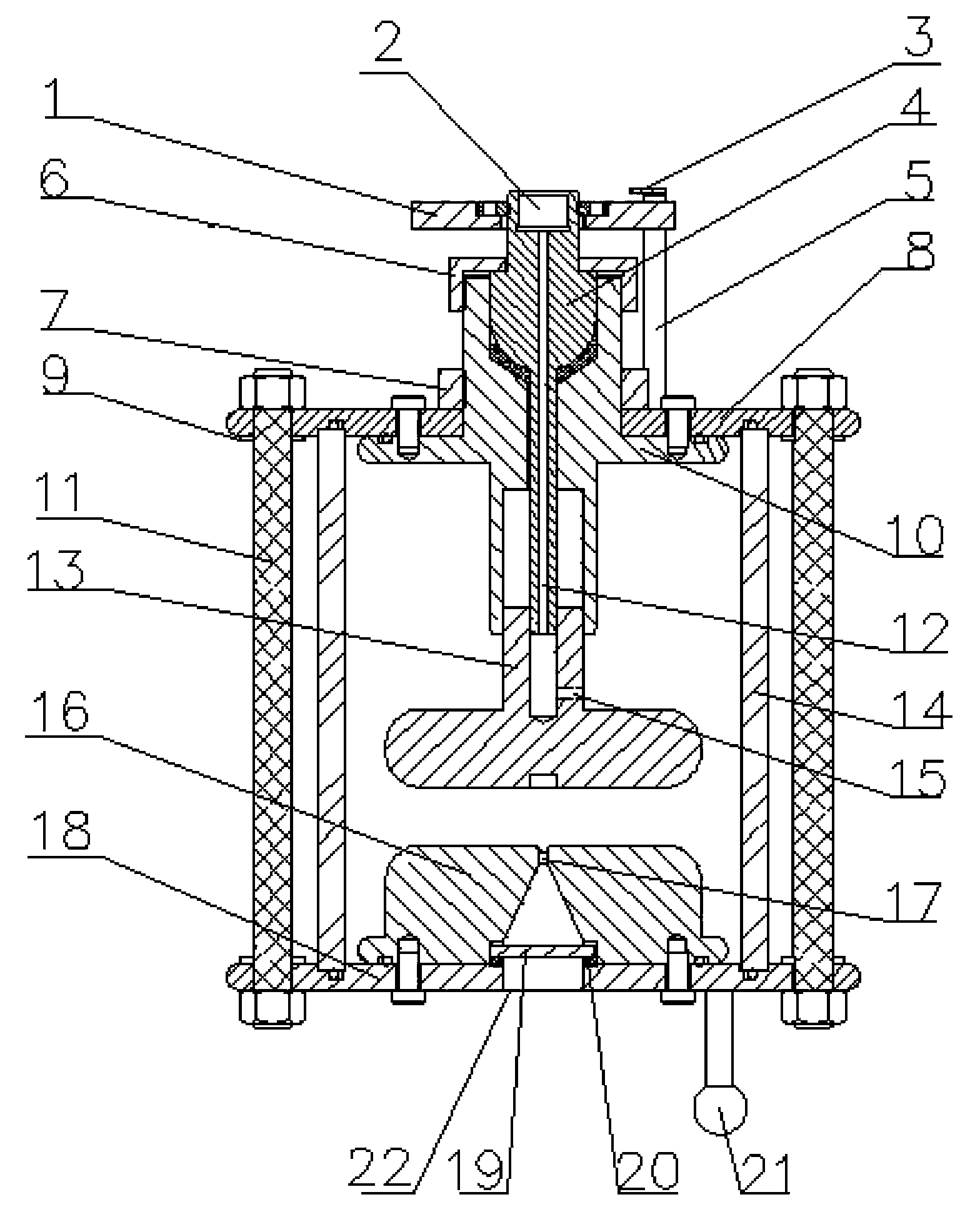
[0014] The laser trigger gas switch proposed by the present invention has a structure such as figure 1 As shown, it includes handwheel 1, reading pointer 3, pointer fixing rod 5, upper electrode seat 10, upper electrode 13, lower electrode 16, sealing sleeve 14, connecting rod 4, metal top plate 8, metal bottom plate 18, support rod 11 , Translucent glass plate 19 and terminal post 21. The metal top plate 8 and the metal bottom plate 18 are supported by the support rods 11, and the shielding rings 9 are respectively installed between the metal top plate 8, the metal bottom plate 18 and the support rods 11. The sealing sleeve 14 is placed between the metal top plate 8 and the metal bottom plate 18 , and a sealed cavity is formed in the sealing sleeve through the sealing rings at the upper and lower ends of the sealing sleeve 14 . The upper electrode holder 10 is fixed at the center of the metal top plate 8, the bottom of the upper electrode holder 10 stretches into the sealed ...


PUM


Abstract

The invention relates to a laser-triggered gas switch, belonging to the technical field of power switches. The laser-triggered gas switch comprises an upper electrode, an upper electrode holder, a lower electrode, a transparent glass plate, supporting rods, a sealing sleeve and the like. The laser-triggered gas switch converts rotation of a hand wheel into transverse movement of the upper electrode by using a connecting rod, so as to change the distance of a spark gap. Scales are marked on the upper electrode and the hand wheel, the distance of the spark gap can be accurately displayed, and adjustment accuracy is related to the pitch of the connecting thread of the connecting rod and the upper electrode and the quantity of scales on the hand wheel. The laser-triggered gas switch can be connected with an external gas valve and a gas pressure meter which are respectively used for filling gas into a sealed shell and displaying gas pressure. Shielding rings are installed at positions where a metal top plate and a metal bottom plate are connected with an insulating nylon rod, and silica gel is coated between the shielding rings and the insulating nylon rod to prevent an obvious corona phenomenon from occurring in external insulation under the situation that the spark gap is under high voltage. The laser-triggered gas switch has the advantages of simple structure, high practicability, stable triggering performance, long service life and convenience in manufacturing.

Description

technical field [0001] The invention relates to a laser trigger gas switch, which belongs to the technical field of electric switches. technical background [0002] The switch is one of the key components of the pulse power device. The performance of the switch directly affects the performance of the pulse power device. The requirements for this type of switch are: high current, high voltage, short delay, frequent action, and long life. When the laser is focused on the trigger gap, the insulating gas around the focus and its vicinity is immediately ionized into a local plasma, which rapidly develops into a plasma channel under the action of an external electric field to close the switch. The laser trigger gas switch has the advantages of small trigger delay and jitter, low probability of pre-breakdown, simple structure, stable and reliable operation, remote control, suitable for repeated operation and multi-gap multi-channel operation, etc. Moreover, the triggering of the l...

Claims


Application Information

Patent Timeline
Patent Type & Authority Patents(China)
IPC IPC(8): H01T2/00H01T1/22
Inventor 孙为民曾嵘盛新富庄池杰
Owner TSINGHUA UNIV
Why Eureka
Try Eureka