A dual-channel single-gap plasma spraying device and its application

A technology of plasma and injection device, applied in the field of plasma injection device, can solve the problems of low injection gap energy, increase the difficulty of ignition gap, etc., and achieve the effects of long injection distance, simple structure and stable trigger performance

Active Publication Date: 2021-11-19
XI AN JIAOTONG UNIV
View PDF7 Cites 0 Cited by
  • Summary
  • Abstract
  • Description
  • Claims
  • Application Information

AI Technical Summary

Problems solved by technology

For applications with long distances and low work coefficients, the above-mentioned triggering methods all have the disadvantage of low energy injected into the gap, which increases the difficulty of igniting the gap

Method used


Image

  • A dual-channel single-gap plasma spraying device and its application
  • A dual-channel single-gap plasma spraying device and its application
  • A dual-channel single-gap plasma spraying device and its application

Examples


Embodiment 1

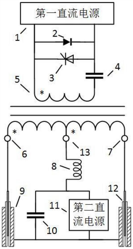
[0049] see figure 1 , a dual-channel single-gap plasma injection device, consisting of a first DC power supply, a freewheeling diode, a thyristor, a pulse capacitor, a pulse transformer, a second DC power supply, a main discharge capacitor, a protection inductor, and two plasma injectors .

[0050] Wherein, the pulse capacitor has a capacitance value of 1 μF, and is charged by the first DC power supply through the primary side of the pulse transformer. The discharge circuit is composed of the parallel circuit of the pulse capacitor, the thyristor and the freewheeling diode, and the primary side of the pulse transformer in series, and provides high-voltage trigger pulse output to the two plasma injectors.

[0051] The main discharge capacitor is charged by the second DC power supply, its capacitance value is 20uF, and its charging voltage is 3kV. When the thyristor is turned on, the pulse capacitor is discharged through the thyristor and the primary side of the pulse transfor...

Embodiment 2

[0057] see figure 1 , a dual-channel single-gap plasma injection device, consisting of a first DC power supply, a freewheeling diode, a thyristor, a pulse capacitor, a pulse transformer, a second DC power supply, a main discharge capacitor, a protection inductor, and two plasma injectors .

[0058] Wherein, the pulse capacitor has a capacitance value of 4 μF, and is charged by the first DC power supply through the primary side of the pulse transformer. The discharge circuit is composed of the parallel circuit of the pulse capacitor, the thyristor and the freewheeling diode, and the primary side of the pulse transformer in series, and provides high-voltage trigger pulse output to the two plasma injectors.

[0059] The main discharge capacitor is charged by the second DC power supply, its capacitance value is 60uF, and the charging voltage is 2kV. When the thyristor is turned on, the pulse capacitor is discharged through the thyristor and the primary side of the pulse transfor...

Embodiment 3

[0065] see figure 1 , a dual-channel single-gap plasma injection device, consisting of a first DC power supply, a freewheeling diode, a thyristor, a pulse capacitor, a pulse transformer, a second DC power supply, a main discharge capacitor, a protection inductor, and two plasma injectors .

[0066]Wherein, the pulse capacitor has a capacitance value of 4 μF, and is charged by the first DC power supply through the primary side of the pulse transformer. The discharge circuit is composed of the parallel circuit of the pulse capacitor, the thyristor and the freewheeling diode, and the primary side of the pulse transformer in series, and provides high-voltage trigger pulse output to the two plasma injectors.

[0067] The main discharge capacitor is charged by the second DC power supply, its capacitance value is 120uF, and the charging voltage is 1kV. When the thyristor is turned on, the pulse capacitor is discharged through the thyristor and the primary side of the pulse transfor...


PUM

PropertyMeasurementUnit
diameteraaaaaaaaaa
lengthaaaaaaaaaa
capacitanceaaaaaaaaaa

Abstract

The invention discloses a dual-channel single-gap plasma injection device and its application. The plasma injection device is triggered synchronously by pulse discharge, and the capillary discharge in the plasma injector ablates insulating gas-generating materials through a large capacitor with initial energy storage. The process is powered, and a large amount of plasma is continuously generated. Based on the huge pressure difference inside and outside the capillary, a high-temperature, high-pressure, and high-density plasma jet is formed. The device adopts single-gap capillary discharge injection, with simple structure, long injection distance and stable trigger performance, which can effectively meet the gap trigger requirements under long distance and low working coefficient. Increasing the capacitance of the main discharge capacitor can increase the pulse width and current duration of the discharge current in the capillary, thereby prolonging the duration of the plasma injection, which plays an important role in the reliable triggering of the gap.

Description

technical field [0001] The invention belongs to the technical field of pulse power, and in particular relates to a dual-path single-gap plasma injection device and its application. Background technique [0002] With the development of pulse power technology, gas gaps have been widely studied and applied, and can be used as switching devices for high-voltage pulse formation, high-voltage pulse steepening switches, or overvoltage protection equipment for power equipment. The performance of the gas gap is often affected by the circuit parameters and the atmospheric environment, such as changes in temperature, humidity or pressure will affect the self-breakdown performance of the gap. When the working voltage is much lower than the self-breakdown voltage and the low working coefficient state, the gas gap is sometimes extended and jittery, which affects the reliability of the gap breakdown. [0003] Existing gas gaps often use forced triggering means, such as using small gap spa...

Claims


Application Information

Patent Timeline
Patent Type & Authority Patents(China)
IPC IPC(8): H05H1/36H05H1/44
CPCH05H1/36H05H1/44H05H1/3494
Inventor 杨兰均魏鹏曹博韩佳一路志建
Owner XI AN JIAOTONG UNIV
Why Eureka
Try Eureka