Silicon controlled rectifier combination switch

A composite switch and thyristor technology, applied in reactive power compensation, reactive power adjustment/elimination/compensation, etc., can solve problems such as unreliable operation and failure to meet the conduction conditions of thyristor

Active Publication Date: 2015-04-08
南京鹰纳视机器人有限公司
View PDF12 Cites 0 Cited by
  • Summary
  • Abstract
  • Description
  • Claims
  • Application Information

AI Technical Summary

Problems solved by technology

The patent specifically describes that in the conduction process, the thyristor only has a trigger signal, but there is no voltage drop, and the conduction condition of the thyristor is not satisfied, that is, there is no voltage drop between the anode A and the cathode K of the thyristor, so , the compensation device with this structure cannot operate reliably under dynamic conditions

Method used


Image

  • Silicon controlled rectifier combination switch
  • Silicon controlled rectifier combination switch
  • Silicon controlled rectifier combination switch

Examples


Embodiment 1

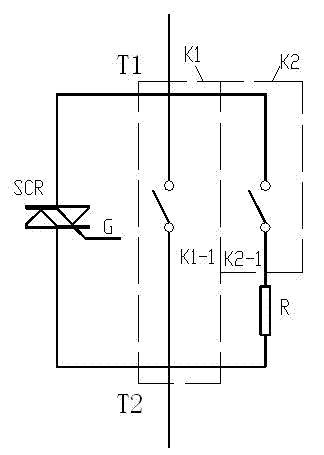
[0043] Such as figure 1 As shown, a thyristor composite switch includes a two-way thyristor SCR and a first electromagnetic switch K1, the two-way thyristor SCR has a control terminal G and a first main terminal T1 and a second main terminal T2, and the two-way The first main terminal T1 and the second main terminal T2 of the thyristor SCR are connected in parallel with the two ends of the normally open contact K1-1 of the first electromagnetic switch K1, and also include a second electromagnetic switch K2 and a resistor R; the second electromagnetic switch The normally open contact K2-1 of the switch K2 is connected in series with the resistor R; the two ends of the series circuit composed of the normally open contact K2-1 of the second electromagnetic switch K2 and the resistor R are connected in parallel to the normally open contact of the first electromagnetic switch K1. Point K1-1 at both ends.

[0044] The first electromagnetic switch K1 and the second electromagnetic ...

Embodiment 2

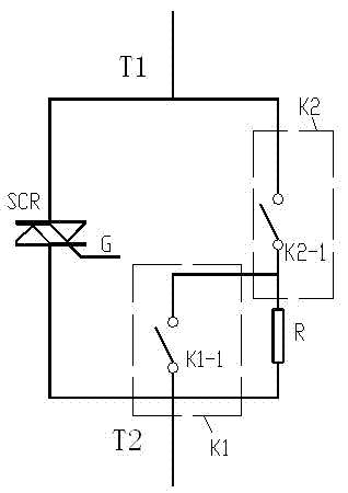
[0049] Such as figure 2 As shown, a thyristor composite switch includes a bidirectional thyristor SCR and a first electromagnetic switch K1, the bidirectional thyristor SCR has a control terminal G and a first main terminal T1 and a second main terminal T2, and also includes The second electromagnetic switch K2 and resistor R; the normally open contact K2-1 of the second electromagnetic switch K2 is connected in series with the resistor R; The first main terminal T1 and the second main terminal T2 of the thyristor SCR are connected in parallel; the two ends of the normally open contact K1-1 of the first electromagnetic switch K1 are connected in parallel with the two ends of the resistor R.

[0050] The first electromagnetic switch K1 and the second electromagnetic switch K2 of the present invention are relays or contactors.

[0051] Of course, the present invention preferably selects the magnetic latching relay.

[0052] When the embodiment 2 is used, the following uses th...

Embodiment 3

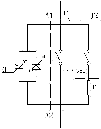
[0056] Such as image 3 As shown, a thyristor composite switch includes two one-way thyristors SCR1, SCR2, and a first electromagnetic switch K1, and the two one-way thyristors SCR1, SCR2 respectively have a control terminal G1 and a control terminal G2, and two unidirectional thyristors SCR1 and SCR2 are connected in reverse parallel to form the first terminal A1 and the second terminal A2, and two unidirectional thyristors SCR1 and SCR2 are connected in reverse parallel and form the first terminal A1 and the second terminal A2 are connected in parallel with the two ends of the normally open contact K1-1 of the first electromagnetic switch K1, and also include a second electromagnetic switch K2 and a resistor R; the normally open contact K2- of the second electromagnetic switch K2 1 is connected in series with the resistor R; the two ends of the series circuit formed by the normally open contact K2-1 of the second electromagnetic switch K2 and the resistor R are connected in ...


PUM


Abstract

The invention discloses a silicon controlled rectifier combination switch. The silicon controlled rectifier combination switch comprises a bidirectional silicon controlled rectifier (SCR), a first electromagnetic switch K1, a second electromagnetic switch K2 and a resistor R. The bidirectional SCR is provided with a control end G, a first main terminal T1 and a second main terminal T2, wherein the first main terminal T1 and the second main terminal T2 of the bidirectional SCR are in parallel connection with two ends of a normally opened contact K1-1 of the first electromagnetic switch K1. A normally opened contact K2-1 of the second electromagnetic switch K2 is in series connection with the resistor R. Two ends of a series circuit formed by the normally opened contact K2-1 of the second electromagnetic switch K2 and the resistor R are connected to two ends of the normally opened contact K1-1 of the first electromagnetic switch K1 in parallel. The silicon controlled rectifier combination switch has the advantages of achieving zero-current silicon controlled rectifier breakover, being reliable in switching process and the like.

Description

technical field [0001] The invention relates to a thyristor composite switch, which is a device for controlling switching of capacitors and an important part of a reactive power compensation device for a power grid, and the performance of the switching element has a great influence on the reliability of the reactive power compensation device plays a very important role. Background technique [0002] In the implementation process of power grid transformation, it is often necessary to add a shunt capacitor reactive power compensation device, which plays a positive role in improving the quality of power supply voltage, tapping the potential of power supply equipment, reducing line loss and saving energy. [0003] Most of the early reactive power compensation devices used switching methods such as AC contactors and thyristor electronic switches. AC contactors will generate large inrush currents and overvoltages when capacitors are switched on and off, and transient high voltages...

Claims


Application Information

Patent Timeline
Patent Type & Authority Patents(China)
IPC IPC(8): H02J3/18
CPCY02E40/30
Inventor 顾金华
Owner 南京鹰纳视机器人有限公司
Why Eureka
Try Eureka