Connector and female end thereof

A technology of connectors and female ends, which is applied in the direction of sleeve/socket connection, pipe/pipe joint/fitting, valve housing structure, etc., and can solve the problems of poor sealing reliability and so on

Pending Publication Date: 2022-06-24
SHENZHEN ENVICOOL SMART CONNECTION TECH CO LTD
View PDF0 Cites 0 Cited by
  • Summary
  • Abstract
  • Description
  • Claims
  • Application Information

AI Technical Summary

Problems solved by technology

In current connectors, too many sealing structures (such as sealing rings) are used, resulting in poor sealing reliability

Method used


Image

  • Connector and female end thereof
  • Connector and female end thereof
  • Connector and female end thereof

Examples


Embodiment Construction

[0029] The embodiment of the present invention discloses a female end of a connector, which can effectively solve the problem of excessive and unreliable internal sealing structures of the female end.

[0030] The technical solutions in the embodiments of the present invention will be clearly and completely described below with reference to the accompanying drawings in the embodiments of the present invention. Obviously, the described embodiments are only a part of the embodiments of the present invention, but not all of the embodiments. Based on the embodiments of the present invention, all other embodiments obtained by those of ordinary skill in the art without creative efforts shall fall within the protection scope of the present invention.

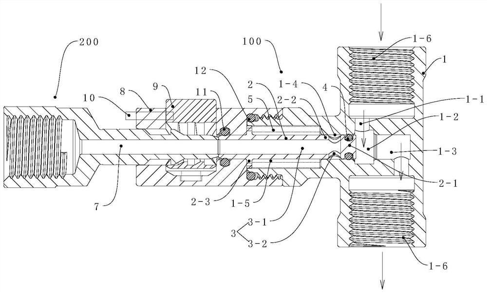
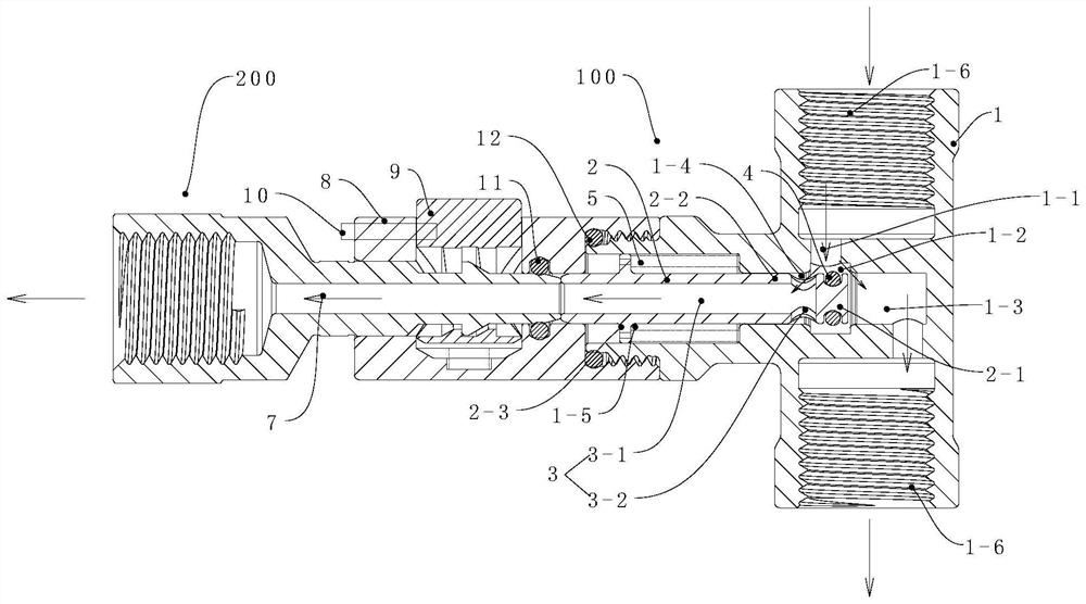
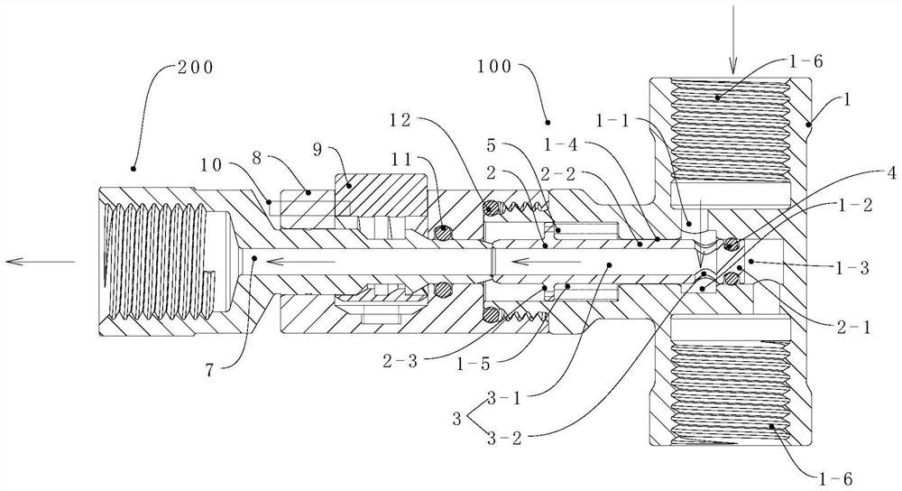
[0031] see Figure 1-Figure 4 , figure 1 A schematic cross-sectional structure diagram of the connector when the shunt channel is closed according to some embodiments of the present invention; figure 2 A schematic cross-sectional st...


PUM


Abstract

The invention discloses a female end of a connector. The female end comprises a main channel piece and a main valve element connected with the main channel piece in a sliding mode. A main inlet channel, a flow dividing cavity and a main outlet channel which are sequentially communicated are formed in the main channel piece, a movable cavity is formed in the position, at the flow dividing cavity, of the main channel piece, the main valve element penetrates through the movable cavity, and a flow dividing channel is formed in the movable cavity. The valve head of the main valve element can slide to block the main outlet channel so that the flow dividing channel can communicate with the flow dividing cavity, and can slide to block the movable cavity so that the flow dividing channel can be disconnected from the flow dividing cavity. The valve head of the main valve element not only can move forwards to block the main outlet channel, but also can block the movable cavity to enable the flow dividing channel and the flow dividing cavity to be disconnected when the valve head of the main valve element retreats. The valve head can be better utilized, other structures do not need to be used for sealing respectively, the sealing performance of the valve head can be fully guaranteed, and therefore the overall using firmness is greatly improved. The invention further discloses a connector comprising the female end.

Description

technical field [0001] The present invention relates to the technical field of pipeline connection, and more particularly, to a female end of a connector, and also to a connector including the above female end. Background technique [0002] In the air braking system of passenger, freight and railway vehicles, the braking principle is mainly to use compressed air to push the brake action, push the brake pads and brake shoes to fit on the wheels for friction, thereby consuming heat energy and realizing deceleration and parking. Therefore, the compressed air pressure is an important indicator to consider the braking performance of the vehicle, and the matching on-board load is another important indicator of the braking performance. The connector is a device that detects the pressure of the compressed air circuit and simulates the weight of the vehicle by introducing compressed air. [0003] The connector is installed in the compressed air circuit and does not affect the normal...

Claims


Application Information

Patent Timeline
Patent Type & Authority Applications(China)
IPC IPC(8): F16L41/16F16L41/02F16L41/10F16L21/08F16K11/07F16K27/04
CPCF16L41/16F16L41/021F16L41/10F16L21/08F16K11/0716F16K27/041
Inventor 陈刚
Owner SHENZHEN ENVICOOL SMART CONNECTION TECH CO LTD
Why Eureka
Try Eureka