Fault detection method for optical fiber links of passive optical networks

A passive optical network and fault detection technology, applied in transmission monitoring/testing/fault measurement systems, electromagnetic wave transmission systems, electrical components, etc., can solve the problems of large optical power loss, high cost, large volume, etc., and achieve long transmission distance, reduce the difficulty of system implementation, and the effect of low insertion loss

Active Publication Date: 2015-05-06
SOUTHEAST UNIV
View PDF2 Cites 0 Cited by
  • Summary
  • Abstract
  • Description
  • Claims
  • Application Information

AI Technical Summary

Problems solved by technology

However, there is a problem with this method, that is, different optical encoders need to be added to the front ends of different ONUs, so that different optical codewords can be used to identify different branches
This requires professionally trained construction personnel to carry out unified system planning and installation, and for the application environment where PON users are scattered, it will still bring certain difficulties in the process of system installation
In addition, the decoding operation performed by the optical decoder at the receiving end will bring a large loss of optical power, and the current optical decoder array has a large volume and high cost

Method used


Image

  • Fault detection method for optical fiber links of passive optical networks
  • Fault detection method for optical fiber links of passive optical networks
  • Fault detection method for optical fiber links of passive optical networks

Examples


Embodiment Construction

[0033] The technical scheme of the present invention is described in detail below in conjunction with accompanying drawing:

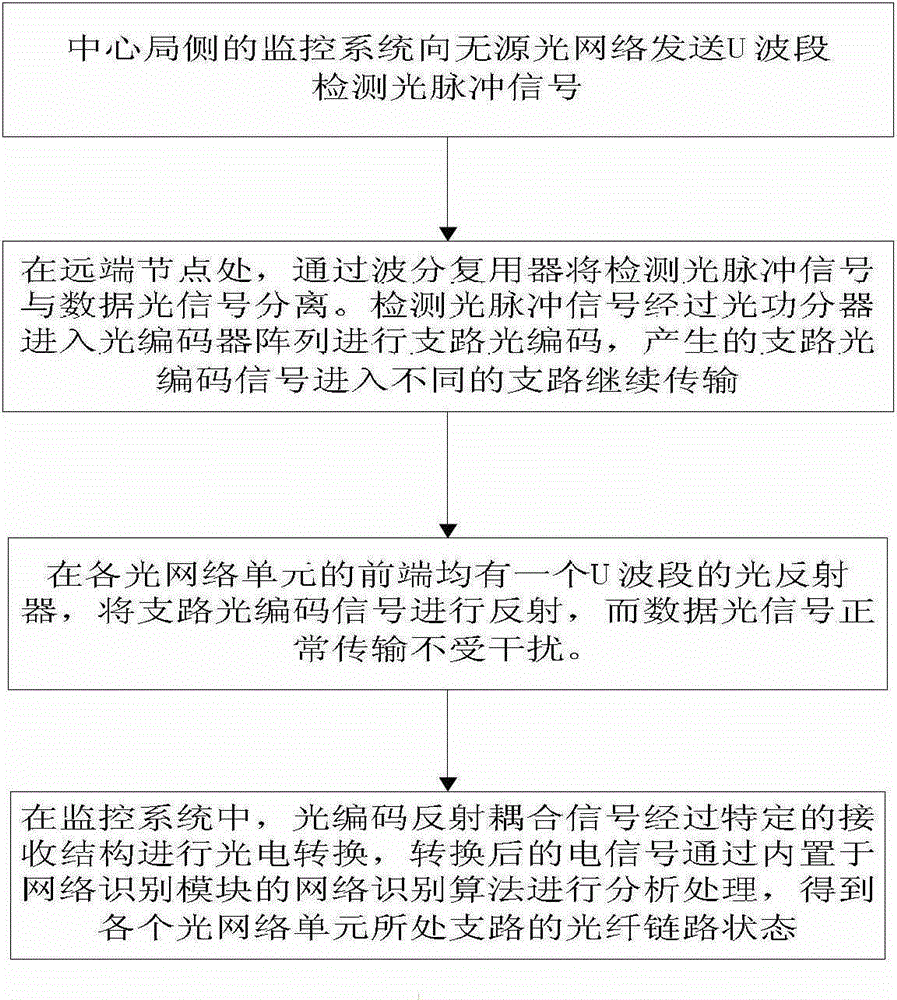
[0034] figure 1 It is a flow chart of the passive optical network fiber link fault detection method of the present invention, comprising the following steps:

[0035] Step 1. The fault detection system on the central office side sends a U-band detection optical pulse signal to the passive optical network;

[0036] Step 2. At the remote node, the detection optical pulse signal is separated from the data optical signal through a wavelength division multiplexer. The detection optical pulse signal enters the optical encoder array through the optical power splitter for optical encoding, and the generated optical encoding signal enters the Different branches continue to transmit, and the optically encoded signals entering different branches are different and orthogonal to each other;

[0037] Step 3. There is a U-band optical reflector at the front end of t...


PUM


Abstract

The invention discloses a fault detection method for optical fiber links of passive optical networks. The method comprises the following steps that: an optical encoder array is placed at a remote node, and after optical coded signals which are different and orthogonal to each other are generated at the remote node, the signals enter into each branch and continues to be transmitted; an optical reflector at the front end of an optical network unit of each branch reflects the optical coded signals back to a fault detection system of a central office; and in the fault detection system of the central office, the photoelectric conversion of the received optical coded signals is completed through a specific electric-domain decoding structure, and then received coded electric signals are processed by using a network recognition algorithm so as to analyze and judge the state of an optical fiber link. According to the invention, the complexity and difficulty of system implementation can be reduced; the decoding operation is completed in an electric domain, thereby improving the power budget of the fault detection system and reducing the system cost.

Description

technical field [0001] The invention relates to a passive optical network (PON) optical fiber link fault detection method, in particular to a PON optical fiber link fault detection method based on optical encoding and electrical domain decoding, and belongs to the technical field of optical fiber communication. Background technique [0002] As the PON is widely used in the optical access network, more and more attention is paid to the fault detection of the optical fiber link status in the optical network. At present, the commonly used optical fiber link test equipment is optical time domain reflectometer (OTDR), but OTDR can only be used in point-to-point optical fiber link test. In a PON using a tree structure and an optical power splitter, the back Rayleigh scattering generated by the detection light pulse sent by the OTDR is a linear superposition of the backscattering signals of each branch. Therefore, the branch where the fault is located cannot be identified, so the ...

Claims


Application Information

Patent Timeline
Patent Type & Authority Patents(China)
IPC IPC(8): H04B10/071H04B10/07
Inventor 孙小菡周谞
Owner SOUTHEAST UNIV
Why Eureka
Try Eureka