Intermediate presser foot lifting structure of pattern-sewing machine

A pattern machine and medium pressure technology, which is applied in the direction of cloth pressing mechanism, sewing machine components, sewing machine control devices, etc., can solve the problems of poor sewing effect and inability to press the sewing material well, so as to ensure the sewing quality Effect

Inactive Publication Date: 2013-03-06
SHANGHAI GUIYI SEWING EQUIP MFG
View PDF0 Cites 2 Cited by
  • Summary
  • Abstract
  • Description
  • Claims
  • Application Information

AI Technical Summary

Problems solved by technology

If you need to sew on materials with different sizes and thicknesses, you need to adjust the intermediate presser assembly according to the thickest material. When sewing, the intermediate presser works at the adjusted height, which cannot be changed and cannot be well adjusted. The sewing material is pressed tightly, and the sewing effect is not good

Method used


Image

  • Intermediate presser foot lifting structure of pattern-sewing machine
  • Intermediate presser foot lifting structure of pattern-sewing machine

Examples


Embodiment Construction

[0008] A preferred embodiment will be given below, and the present invention will be described more clearly and completely in conjunction with the accompanying drawings.

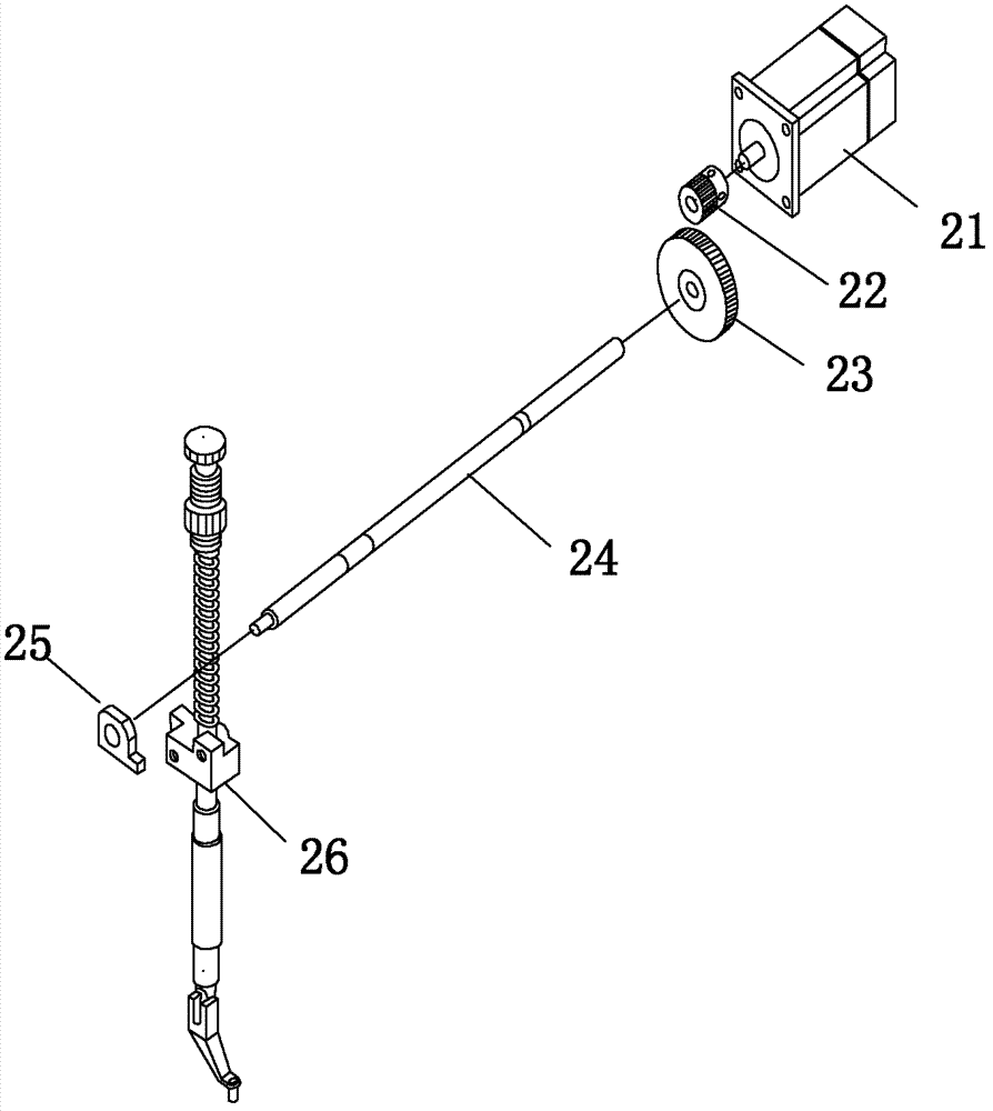
[0009] Such as figure 2 As shown, the lifting structure of the intermediate presser foot of the pattern machine of the present invention includes a controllable motor 21, a driving gear 22, a driven gear 23, an intermediate pressing foot lifting shaft 24, and a lifting connecting rod 25. The controllable motor 21 is connected to the driving gear 22, The driving gear 22 is threadedly connected with the driven gear 23 , one end of the intermediate presser foot lifting shaft 24 is connected with the driven gear 23 , and the other end of the intermediate presser foot lifting shaft 24 is connected with the lifting connecting rod 25 . The lifting link 25 is connected with the intermediate presser foot 26 .

[0010] The controllable motor 21 drives the drive gear 22, the driven gear 22 drives the driven gear 23, ...


PUM


Abstract

The invention discloses an intermediate presser foot lifting structure of a pattern-sewing machine. The intermediate presser foot lifting structure comprises a controllable motor, a driving gear, a driven gear, an intermediate presser foot lifting shaft and a lifting connecting rod, the controllable motor is connected with the driven gear which is in threaded connection with the driven gear, one end of the intermediate presser foot lifting shaft is connected with the driven gear, and the other end of the intermediate presser foot lifting shaft is connected with the lifting connecting rod. By the intermediate presser foot lifting structure of the pattern-sewing machine, height change of an intermediate presser foot can be controlled, and the height of the intermediate presser foot can be changed along with the thickness of materials when the materials different in thickness are sewed.

Description

technical field [0001] The invention relates to a pattern machine, in particular to an intermediate presser foot lifting structure of the pattern machine. Background technique [0002] Such as figure 1 As shown, the existing pattern machines are generally driven by a cylinder or an electromagnet lifting structure to lift the middle presser foot. Because the cylinder 11 (or electromagnet) is fixed on the body, the cylinder joint 12 is fixed on the cylinder rod of the cylinder 11, and is hinged with the connecting rod 14 through the hinge screw 13, and the connecting rod 14 is hinged with the lifting plate 16 through the hinge screw 15, and the lifting plate 16 is fixed on the machine body by the hinge screw 17; when the cylinder rod of the cylinder 11 stretches out and drives the cylinder joint 12 to stretch out, the connecting rod 14 stretches forward, pushing the lifting plate 16 to swing counterclockwise around the hinge screw 17, and the middle presser foot assembly 19 ...

Claims


Application Information

Patent Timeline
Patent Type & Authority Applications(China)
IPC IPC(8): D05B69/00D05B29/02
Inventor 黄志云
Owner SHANGHAI GUIYI SEWING EQUIP MFG
Why Eureka
Try Eureka