Target azimuth determining method

A technology for determining the method and target orientation, which is applied in the direction of measurement devices, mapping and navigation, compass, etc., and can solve problems such as the inability to determine the parking position of the vehicle

Inactive Publication Date: 2013-03-06
XIAN FUAN INNOVATION CONSULTATION
View PDF0 Cites 0 Cited by
  • Summary
  • Abstract
  • Description
  • Claims
  • Application Information

AI Technical Summary

Problems solved by technology

[0002] In many cases, you need to find the target, such as in the parking lot, there are too many parked vehicles, and when you come back to search, it is really impossible to determine the location of the vehicle

Method used


Image

  • Target azimuth determining method
  • Target azimuth determining method
  • Target azimuth determining method

Examples


Embodiment Construction

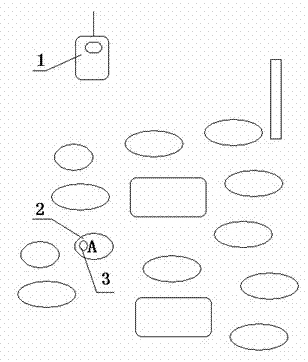
[0019] Such as figure 1 As shown, a method for determining the orientation of a target includes at least one hand-held wireless receiver 1, a target body 2 with a directional antenna and a control circuit 3, the directional antenna is coupled with a motor 303 shaft, and the rotation of the motor shaft drives the directional antenna around The shaft rotates, the control circuit obtains the rotation angle of the motor shaft and processes and calculates the rotation angle to obtain the current azimuth angle, and sends the radio wave carrying the azimuth angle through the directional antenna; when the handheld wireless receiver 1 receives the After the angle of the radio wave, the azimuth is displayed on the display.

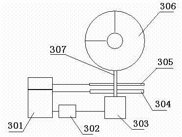
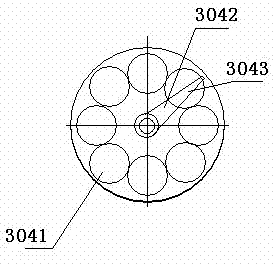
[0020] figure 2 , image 3 As shown, it is a schematic diagram of a directional antenna coupled to a motor shaft. The shaft 307 of the motor 303 is fixed with an encoder 305 and a photoelectric receiving disc 304. The encoder 305 is magnetically or optically enco...


PUM


Abstract

The invention relates to a detection device and particularly relates to a target azimuth determining method. The detection device at least comprises a handheld type wireless receiver (1), a directional antenna and a target body (2) of a control circuit (3); the directional antenna is coupled with a shaft of a motor (303); the shaft of the motor rotates to drive the directional antenna to rotate along the shaft; the control circuit obtains a rotary angle of the shaft of the motor and carries out treatment and calculation on the rotary angle, so as to obtain a current azimuth angle and send a radio wave loaded with the azimuth angle through the directional antenna; and when the handheld type wireless receiver (1) receives the radio wave which is loaded with the azimuth angle and is sent by the directional antenna, the azimuth angle is displayed on a display. According to the target azimuth determining method, azimuth information of positive rotation of the directional antenna is sent out through the directional antenna; after the handheld type wireless receiver receives the azimuth information of the positive rotation of the directional antenna, the azimuth angle is displayed on the display; and the handheld type wireless receiver is held by a hand to determine the azimuth of the target body.

Description

technical field [0001] The invention relates to a detection device, in particular to a target orientation determination method for finding the target orientation. Background technique [0002] In many cases, it is necessary to find the target, such as in the parking lot, there are too many vehicles parked, and when you come back to search, it is really impossible to determine the location of the vehicle. If the pet accidentally runs away, you don't know which direction to run to. [0003] Vision can quickly recognize the observed differentiated objects, but cannot quickly recognize the observed indiscriminate objects. When there is no obvious reference object in the parking lot, the above situation often occurs. Contents of the invention [0004] The purpose of the present invention is to provide a method for determining the orientation of a target, which can quickly find the orientation of the target. [0005] The object of the present invention is achieved in this wa...

Claims


Application Information

Patent Timeline
Patent Type & Authority Applications(China)
IPC IPC(8): G01C17/20G01C17/26
Inventor 刘珉恺曾繁陆
Owner XIAN FUAN INNOVATION CONSULTATION
Why Eureka
Try Eureka