Imaging system and method for localizing a 3d ultrasound volume in a desired orientation

An ultrasound system and ultrasound image technology, applied in the field of medical diagnostic ultrasound systems, can solve problems such as time-consuming and deprivation of time

Active Publication Date: 2020-08-11
KONINKLJIJKE PHILIPS NV
View PDF8 Cites 0 Cited by
  • Summary
  • Abstract
  • Description
  • Claims
  • Application Information

AI Technical Summary

Problems solved by technology

Unfortunately, obtaining a good quality 3D rendering of a child's face can be a frustrating and time-consuming experience that will also take away time spent on the more clinically valuable diagnostic ultrasound scans

Method used


Image

  • Imaging system and method for localizing a 3d ultrasound volume in a desired orientation
  • Imaging system and method for localizing a 3d ultrasound volume in a desired orientation
  • Imaging system and method for localizing a 3d ultrasound volume in a desired orientation

Examples


Embodiment Construction

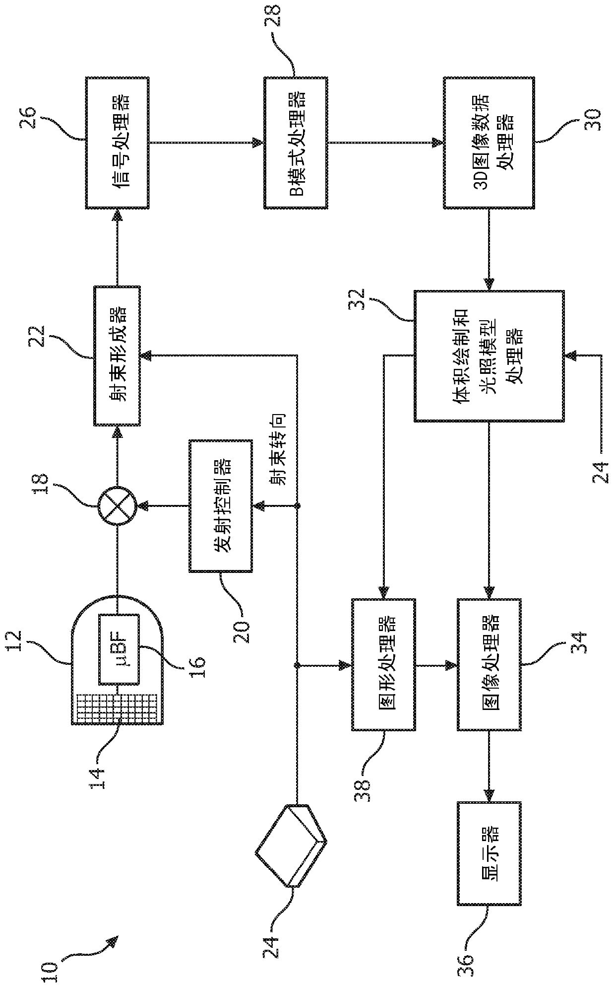
[0009] refer to figure 1 , shows in block diagram form an ultrasound imaging system 10 constructed in accordance with the principles of the present invention. exist figure 1 In the ultrasonic diagnostic imaging system, the ultrasonic probe 12 includes a transducer array 14 for emitting ultrasonic waves and receiving echo information. For example, transducer array 14 can include a two-dimensional array of transducer elements (as shown) that can be scanned in both height and azimuth dimensions for 2D and / or 3D imaging. The transducer array 14 is coupled to a microbeamformer 16 in the probe 12, which controls the transmission and reception of signals by the transducer elements in the array. In this example, the micro beamformer is coupled by a probe cable to a transmit / receive (T / R) switch 18, which switches between transmit and receive and protects the main beamformer 22 from high Energy emission signal effect. In some embodiments, the T / R switch 18 and other components in t...


PUM


Abstract

Methods and systems are provided for displaying a 3D ultrasound image volume in a desired view orientation. 3D ultrasound images of anatomical features in the patient can be acquired. The actual orientation of the anatomical feature in space can be determined. capable of displaying said derived 3D ultrasound image comprising anatomical features such that said anatomical features are positioned at a selected orientation different from said actual orientation and associated with a lighting model for generating lighting and shadows on said anatomical features .

Description

technical field [0001] The present invention relates to medical diagnostic ultrasound systems, and in particular, to imaging systems and methods for displaying 3D ultrasound images in desired view orientations. Background technique [0002] Diagnostic ultrasound applications have continued to improve with the advent of high-resolution 3D rendering of ultrasound data, with better 3D imaging and an enhanced ability to identify tissue features that are not easily identifiable in conventional 2D scanning procedures. Still, the ease and efficiency of specific 3D ultrasound applications needs to be improved. For example, an increasingly important expectation is placed on routine obstetrical ultrasound examinations of mothers who want a 3D rendering of their child's face. Attempting to generate this image is a commercial necessity for many clinicians, and if this service is not available, their patients will go elsewhere. Unfortunately, obtaining a good quality 3D rendering of a ...

Claims


Application Information

Patent Timeline
Patent Type & Authority Patents(China)
IPC IPC(8): A61B8/00A61B8/08G06T19/20
CPCA61B8/0866A61B8/4245A61B8/466A61B8/483A61B8/5215G06T19/20G06T2219/2004G16H50/20
Inventor D·N·朗德西尔
Owner KONINKLJIJKE PHILIPS NV
Why Eureka
Try Eureka