Unlock instant, AI-driven research and patent intelligence for your innovation.

Method for automatic power adjustment of high-power induction type power supply

An inductive power supply and automatic adjustment technology, applied in electrical components, circuit devices, electromagnetic wave systems, etc., can solve problems such as insufficient output of electrical terminals, limited and missing induction range of safe transmission power coils, and excessive transmission power.

Active Publication Date: 2015-01-14
FU TONG TECH
View PDF3 Cites 0 Cited by
  • Summary
  • Abstract
  • Description
  • Claims
  • Application Information

AI Technical Summary

Problems solved by technology

[0002] The inductive power supply (or wireless charger) currently on the market uses two coils, one of which is used as the power supply end for transmitting power, and the other is used as the power receiving end for receiving power. The energy is dangerous and will heat metal objects. The principle is like an induction cooker, and it also affects the phenomenon that the charged object is easily damaged or malfunctioned due to heat.
[0003] In the inductive power supply, in order to operate safely, the power supply terminal and the power receiving terminal must be able to identify each other before starting to supply power. That is, under the requirements of this function, it is necessary to establish control between the power supply terminal and the power receiving terminal. The method of data code transmission, and the transmission function of the data code must be quite stable, so that the power transmission can operate stably, and in the known inductive charging system, the inductive power supply can only be connected between the power supply coil and the power receiving coil When the relative distance between the coils is changed, the output power of the power supply cannot be effectively changed so that the receiving end can receive stable energy, so when the distance between the relative positions of the coils changes, it will not be able to transmit limits
In addition, in the high-power inductive power supply, the output power will be increased or reduced due to the change of the output demand of the receiving end, and the demand for changing the power of the receiving end needs to be adjusted by operating the power supply end through wireless induction. , since there is no physical signal line connection, it will be quite difficult to control
[0004] Therefore, how to solve the problem of safe power transmission in the existing electronic devices when inductively transmitting power and the lack of a limited coil induction range, and the power cannot be changed according to the demand of the receiving end during power supply, so that the transmission power is too large resulting in poor efficiency or The transmission power is too small, which is troubled by the insufficient output of the power terminal, which is the direction that relevant manufacturers in this industry want to study and improve.

Method used


Image

  • Method for automatic power adjustment of high-power induction type power supply
  • Method for automatic power adjustment of high-power induction type power supply
  • Method for automatic power adjustment of high-power induction type power supply

Examples


Embodiment Construction

[0055] In order to achieve the above-mentioned purpose and effect, the technical means and structure adopted by the present invention, the features, functions and implementation methods of the preferred embodiments of the present invention will be described in detail as follows, so as to fully understand.

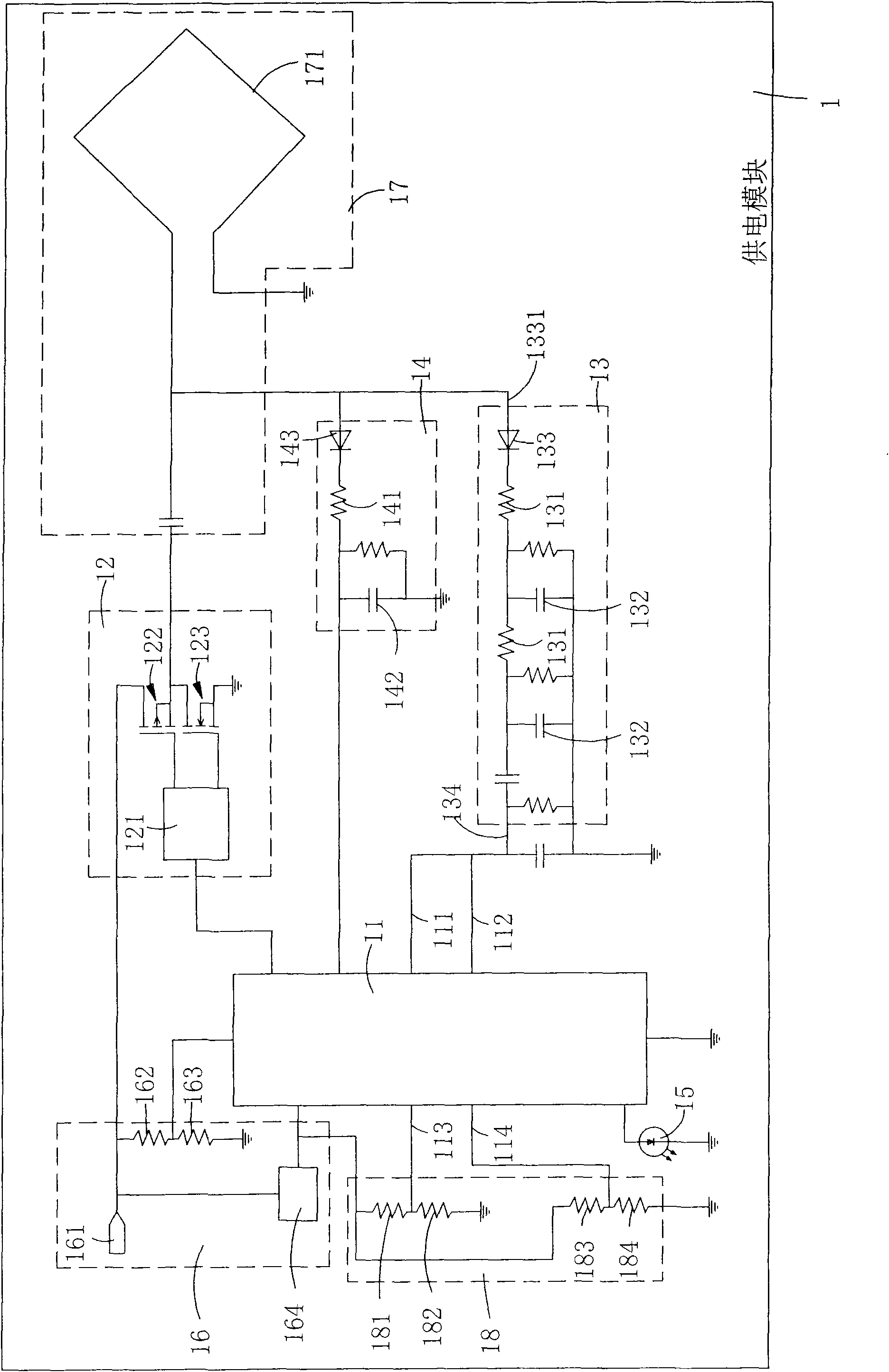
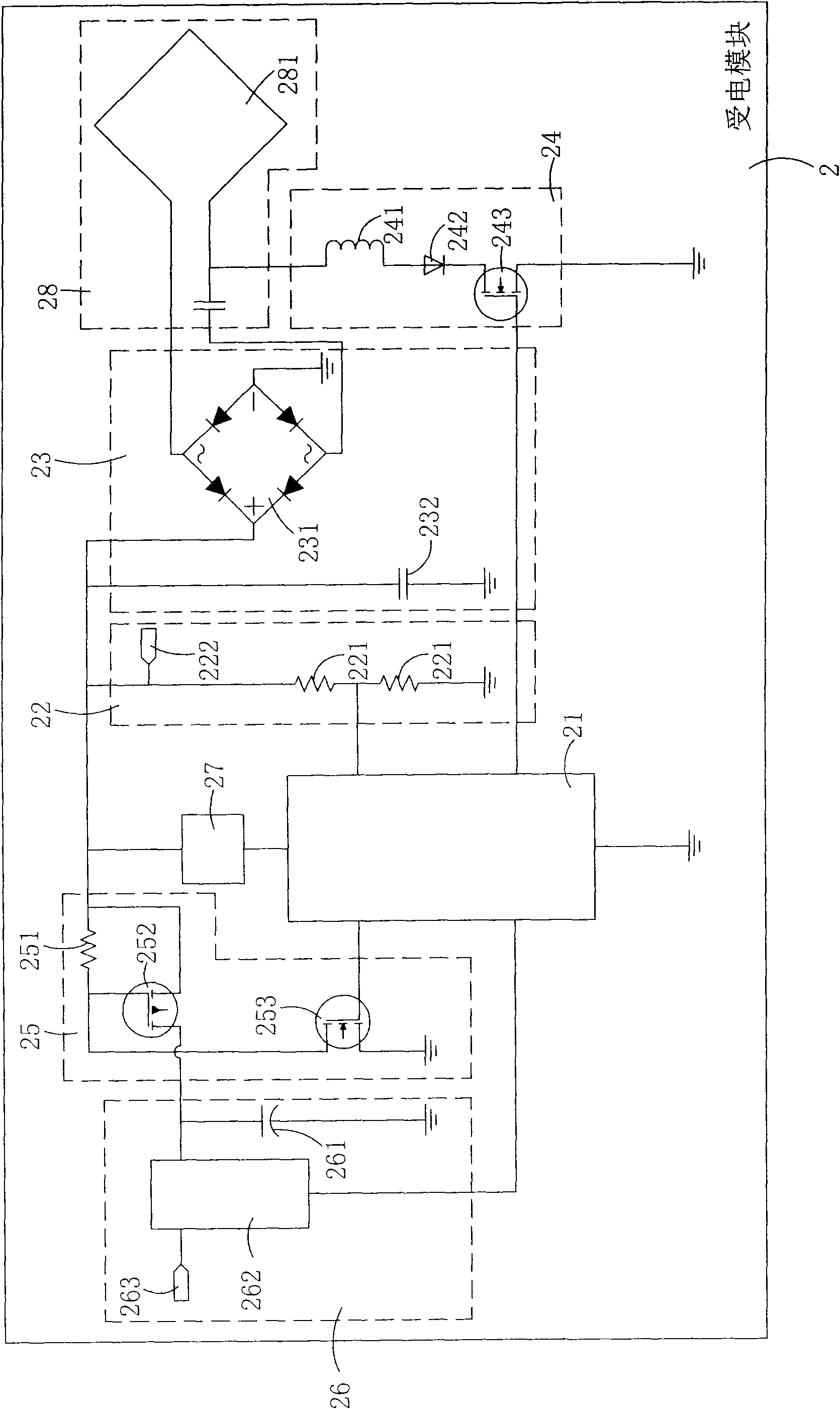
[0056] see figure 1 , 2 As shown, it is a simple circuit diagram of the power supply module and a simple circuit diagram of the power receiving module of the present invention. It can be clearly seen from the figures that the wireless induction device of the present invention includes a power supply module 1 and a power receiving module 2, wherein:

[0057] The power supply module 1 has a power supply microprocessor 11, and the power supply microprocessor 11 is provided with related software programs such as an operation program, a control program, a data code analysis software, an output program of a digital logic level, and an automatic power adjustment program of a power...


PUM


Abstract

The invention relates to a method for automatic power adjustment of a high-power induction type power supply. A power supply module of the power supply is characterized in that a power supply microcontroller is electrically connected with a power supply drive unit, a signal analyzing circuit, a coil voltage detecting circuit, a display unit, a power supply unit and a power supply ground terminal, the power supply drive unit is electrically connected with a resonance circuit and a power supply coil, the power supply coil is used for inducing a power receiving coil of a power receiving module to transmit power supply and data signals, and a power receiving microcontroller of the power receiving module is electrically connected with a voltage detecting circuit, a breakage protection circuit, a voltage stabilizing circuit, an amplitude-modulated carrier modulation circuit, a direct current step-down transformer and rectifying filter circuit and a resonance circuit. By synchronous transmission of power supply and data signals between the power supply module and the power receiving module and using data codes to build an automatic power adjusting program inside through the processors, power transmitted from the power supply module to the power receiving module can be corrected, and automatic power adjustment of the power receiving module can be achieved.

Description

technical field [0001] The present invention provides a method for automatically adjusting power in a high-power inductive power supply, especially for power adjustment by transmitting data signals through induction. When the power supply module and the power receiving module transmit power and data signals synchronously, the power supply module After the sensor receives the data signal, it automatically analyzes, processes and automatically adjusts the power. Background technique [0002] The inductive power supply (or wireless charger) currently on the market uses two coils, one of which is used as the power supply end for transmitting power, and the other is used as the power receiving end for receiving power. The energy is dangerous and will heat metal objects. The principle is like an induction cooker, and it also affects the phenomenon that the charged object is easily damaged or malfunctioned due to heat. [0003] In the inductive power supply, in order to operate sa...

Claims


Application Information

Patent Timeline
Patent Type & Authority Patents(China)
IPC IPC(8): H02J17/00H02J50/12
Inventor 蔡明球詹其哲
Owner FU TONG TECH