Supercharge Your Innovation With Domain-Expert AI Agents!

Method for changing core network nodes for mobile relay users

A core network node and mobile relay technology, applied in network data management, network traffic/resource management, electrical components, etc., can solve the problem of reducing the burden of UE data transmission resources, and cannot effectively relieve the transmission pressure of S5/S8 interface transmission resources. , without considering the UE and other issues, to achieve the effect of reducing the burden of transmission resources

Inactive Publication Date: 2013-03-06
POTEVIO INFORMATION TECH
View PDF3 Cites 2 Cited by
  • Summary
  • Abstract
  • Description
  • Claims
  • Application Information

AI Technical Summary

Problems solved by technology

[0011] In the above process, the trigger condition for MME to unload UE does not take into account the burden of UE data transmission resources, and it cannot unload UE in a targeted manner according to the status of UE, so it cannot effectively relieve the transmission pressure of S5 / S8 interface transmission resources
[0012] In addition, when the UE moves with the base station in a large range, the new MME is different from the MMEPool to which the original MME belongs, and how to determine the new MME Pool for the UE is currently not considered.

Method used


Image

  • Method for changing core network nodes for mobile relay users
  • Method for changing core network nodes for mobile relay users
  • Method for changing core network nodes for mobile relay users

Examples


Embodiment 1

[0055] In this embodiment, when a core network node is changed, a new UE MME is selected through the MRN accessed by the UE.

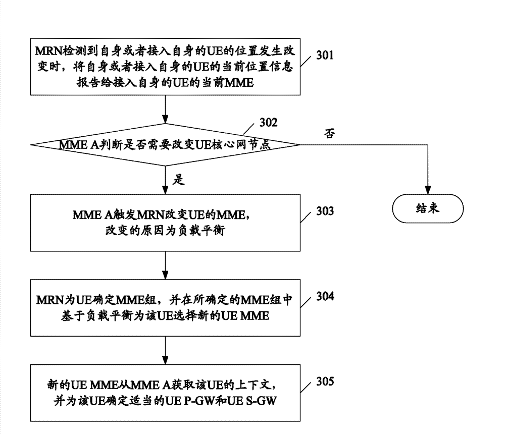
[0056] image 3 It is a specific flow chart of the method for changing the core network node of the mobile relay user in this embodiment. Such as image 3 As shown, the method includes:

[0057] Step 301 , when the MRN detects that the location of itself or the UE that accesses itself changes, it reports the current location information of itself or the UE that accesses itself to the current MME of the UE that accesses itself.

[0058] Here, usually the UE and the MRN it accesses are at the same location, therefore, the location information of the UE and the MRN it accesses is the same. Specifically, the location information may be: the eNB ID / DeNB Global eNB ID of the DeNB accessed by the MRN; the TAI / ECGI / CSG ID of the cell accessed by the MRN; the MME Group ID of the MME serving the MRN (the MRN can obtain GUMMEI obtains this information); Geogr...

Embodiment 2

[0082] In this embodiment, when the core network node is changed, the current MME of the UE selects a new UE MME.

[0083] Figure 4 It is a specific flow chart of the method for changing the core network node of the mobile relay user in this embodiment. like Figure 4 As shown, the method includes:

[0084] Step 401 , when the MRN detects that the location of itself or the UE that accesses itself changes, it reports the current location information of itself or the UE that accesses itself to the current MME of the UE that accesses itself.

[0085] In step 402, after receiving the current location information, MME A judges whether it is necessary to change the UE core network node, if yes, executes step 403, otherwise ends the process.

[0086] The processing of steps 401-402 is the same as the processing of steps 301-302 in the first embodiment, and will not be repeated here.

[0087] In step 403, the current MME of the UE determines a new MME group for the UE, and select...


PUM


Abstract

The invention provides a method for changing core network nodes for mobile relay users. The method includes: an MRN (mobile relay node) detects change in current location and transmits change information to a current MME (mobility management entity) of UE (user equipment); the MME of the UE needing to be changed is determined according to the location information received by the current MME and other preset information of the UE, and change to the MME of the UE is triggered; a new MME group is selected for the UE through the MRN or the current MME, a new MME is selected from the new MME group on the basis of load balance; the new MME acquires UE context from the current MME, and UE P-GW (packet data network gateway) and UE S-GW (serving gateway) are determined for the UE. Core network nodes can be changed for the UE under the MRN by the method while a base station is unchanged by the UE, and transmission source load of UE data is effectively decreased.

Description

technical field [0001] The invention relates to the technology in the mobile relay system, in particular to a method for changing the core network node of the mobile relay user. Background technique [0002] When the user takes the high-speed rail, the LTE UE accesses the LTE network through the MRN deployed on the high-speed rail and accesses the external network through the UE P-GW in the LTE network. figure 1 A self-backhaul network architecture is given to support UE under MRN to access external networks. Among them, the MRN accesses the MRN backhaul transmission network (including the DeNB and the MME / S-GW / P-GW serving the MRN) through the DeNB, and connects to the MME / S-GW serving the UE under the MRN through the MRN backhaul transmission network, and the UE then The external network is accessed by the UE P-GW. The two thick curves in the figure respectively represent S1-C between MRN and UE MME and S1-U between MRN and UE S-GW. [0003] figure 2 It is a schematic...

Claims


Application Information

Patent Timeline
Patent Type & Authority Applications(China)
IPC IPC(8): H04W8/02H04W28/08H04W76/02
Inventor 李婷陈喆潘瑜张欢张莉莉
Owner POTEVIO INFORMATION TECH
Features
  • R&D
  • Intellectual Property
  • Life Sciences
  • Materials
  • Tech Scout
  • Unparalleled Data Quality
  • Higher Quality Content
  • 60% Fewer Hallucinations
Learn More