Magnetic material powder forming device and method
A magnetic material and powder technology, applied in the field of magnetic material powder molding device, can solve problems such as easy cracks, achieve the effect of eliminating pressure and avoiding difficult demoulding
- Summary
- Abstract
- Description
- Claims
- Application Information
AI Technical Summary
Problems solved by technology
Method used
Image
Examples
Embodiment 1
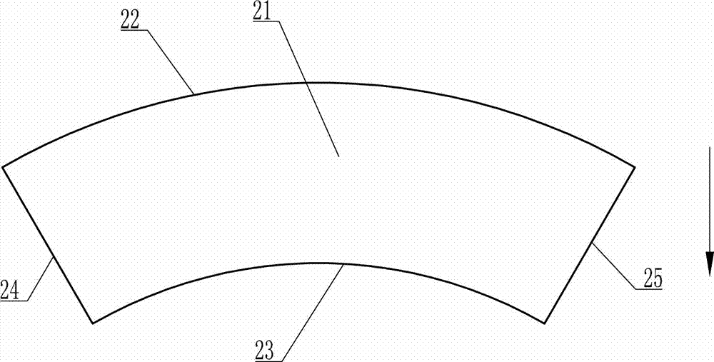
[0047] A magnetic material powder molding die, which includes a female mold, the female mold includes a front side plate 221, a rear side plate 241, a left pressure head 224 and a right pressure head 225, the front side plate 221, the rear side plate Side plate 241, upper cover plate 222, ejector block 223, described left indenter 224, described right indenter 225 and base plate 227 encircle mold cavity, and the shape of described mold cavity is the shape of tile-shaped blank 226, so The shape of the forming surface of the upper cover plate 222 is the same as that of the convex cylindrical surface 22 of the tile-shaped blank 226, and the shape of the forming surface of the ejector block 223 is the same as that of the concave cylindrical surface or plane 23 of the tile-shaped blank 226. The shape of the forming surface of the indenter 224 is the same as that of the left curved surface 24 of the tile-shaped blank 226, the shape of the forming surface of the right indenter 225 is ...
Embodiment 2
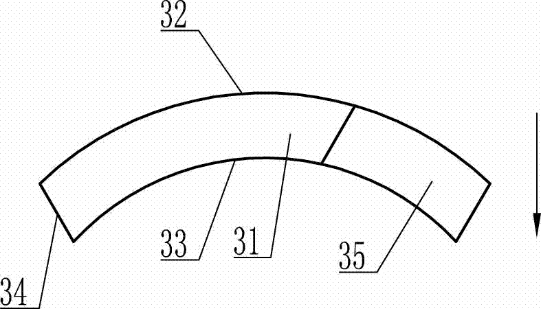
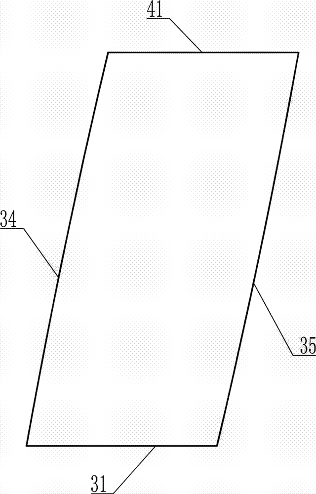
[0049] A magnetic material powder molding die, which includes a female mold, the female mold includes a front side plate 331, a rear side plate 341, a left pressure head 334 and a right pressure head 335, the front side plate 331, the rear side plate 331 Side plate 341, upper cover plate 332, ejector block 333, described left indenter 334, described right indenter 335 and base plate 337 encircle mold cavity, and the shape of described mold cavity is the shape of tile-shaped blank 336, so The shape of the forming surface of the upper cover plate 332 is the same as that of the convex cylindrical surface 32 of the tile-shaped blank 336, and the shape of the forming surface of the ejector block 333 is the same as that of the concave cylindrical surface or plane 33 of the tile-shaped blank 336. The shape of the forming surface of the indenter 334 is the same as that of the left curved surface 34 of the tile-shaped blank 336, the shape of the forming surface of the right indenter 335...
Embodiment 3
[0051] A magnetic material powder molding die, which includes a female mold, the female mold includes a front side plate 221, a rear side plate 241, a left pressure head 224 and a right pressure head 225, the front side plate 221, the rear side plate Side plate 241, upper cover plate 222, ejector block 223, described left indenter 224, described right indenter 225 and base plate 227 encircle mold cavity, and the shape of described mold cavity is the shape of tile-shaped blank 226, so The shape of the forming surface of the upper cover plate 222 is partly the same as the shape of the convex cylindrical surface 22 of the tile-shaped blank 226, and the shape of the forming surface of the ejector block 223 is the same as the shape of the concave cylindrical surface or plane 23 of the tile-shaped blank 226. The shape of the forming surface of the left indenter 224 is the same as that of the left curved surface 24 of the tile-shaped blank 226 and the shape of part of the adjacent out...
PUM
 Abstract
Description
Claims
Application Information
 - R&D
- Intellectual Property
- Life Sciences
- Materials
- Tech Scout
- Unparalleled Data Quality
- Higher Quality Content
- 60% Fewer Hallucinations
Browse by: Latest US Patents, China's latest patents, Technical Efficacy Thesaurus, Application Domain, Technology Topic, Popular Technical Reports.
© 2025 PatSnap. All rights reserved.Legal|Privacy policy|Modern Slavery Act Transparency Statement|Sitemap|About US| Contact US: help@patsnap.com


