Supercharge Your Innovation With Domain-Expert AI Agents!

Driving force transmission apparatus

一种传递装置、驱动力的技术,应用在动力装置、气压力动力装置、通用动力装置的多个不同原动机的布置等方向,能够解决主离合器离合器动作响应性降低、燃料消耗率恶劣、无法获得离合器动作等问题

Inactive Publication Date: 2013-03-13
JTEKT CORP
View PDF6 Cites 7 Cited by
  • Summary
  • Abstract
  • Description
  • Claims
  • Application Information

AI Technical Summary

Problems solved by technology

As a result, swivelability and fuel consumption are adversely affected, and when a four-wheel drive vehicle shifts from a two-wheel drive state to a four-wheel drive state, good clutch operation by the clutch cannot be obtained.
[0014] On the other hand, in order to suppress the adverse effects of the above-mentioned drag torque, it is conceivable, for example, to expand the gap between two adjacent clutch plates among the clutch plates of the main clutch, but in this case, the Reduced responsiveness of clutch action

Method used


Image

  • Driving force transmission apparatus
  • Driving force transmission apparatus
  • Driving force transmission apparatus

Examples


no. 1 approach

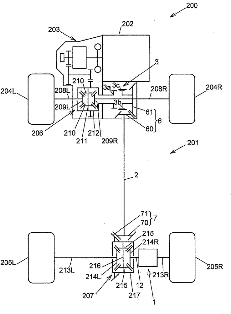
[0036] figure 1 Indicates the outline of a four-wheel drive vehicle. The four-wheel drive vehicle 200 includes a driving force transmission system 201 , an engine 202 , a transmission 203 , front wheels 204L and 204R as main drive wheels, and rear wheels 205L and 205R as auxiliary drive wheels.

[0037] The driving force transmission system 201 is arranged along the driving force transmission path from the transmission 203 side to the rear wheels 205L, 205R side in the four-wheel drive vehicle 200 together with the front differential 206 and the rear differential 207, and is mounted on the four-wheel drive vehicle 200. The body of the car 200 (not shown).

[0038] Moreover, the driving force transmission system 201 has: the driving force transmission device 1, the propeller shaft 2 and the driving force interruption device 3, and is configured to be able to switch the four-wheel drive state of the four-wheel drive vehicle 200 to the two-wheel drive state, or to The two-wheel...

no. 2 approach

[0142] Next, combine Figure 9 ~ Figure 14A as well as Figure 14B A driving force transmission device according to a second embodiment of the present invention will be described. Figure 9 as well as Figure 10 Indicates the entire driving force transmission device. Figure 11 Indicates the rear case. Figure 12 Indicates the first element in the rear housing. Figure 13 Indicates the second element in the rear housing. Figure 14A as well as Figure 14B Indicates the third element in the rear housing. exist Figure 9 ~ Figure 1 4 and Figure 14B In the pair with figure 2 as well as image 3 Components with the same or equivalent functions are denoted by the same symbols, and detailed descriptions are omitted.

[0143] Such as Figure 9 as well as Figure 10 As shown, the driving force transmission device 190 according to the second embodiment of the present invention and the driving force transmission device shown in the first embodiment in which the open type ...


PUM


Abstract

A driving force transmission apparatus (1) includes: a first cam mechanism (15) that converts rotational force from a housing (12) into first cam thrust force (P1) used as clutch force of a main clutch (8) when the first cam mechanism (15) is actuated through clutch action of a pilot clutch (10); and a second cam mechanism (16) that is actuated prior to conversion of the rotational force into the first cam thrust force by the first cam mechanism (15), and that generates second cam thrust force (P2) for reducing an interval between clutch plates of the main clutch (8). The second cam mechanism (16) includes an input cam member (160) that rotates upon receiving rotational force used as actuating force of the input cam member (160) from a cam actuating driving source (5), and an output cam member (161) that generates the second cam thrust force (P2) between the output cam member (161) and the input cam member (160) and outputs the second cam thrust force (P2).

Description

technical field [0001] The present invention relates to a driving force transmission device. Background technique [0002] Japanese Patent Application Laid-Open No. 2003-014001 discloses, as a conventional driving force transmission device, a device that is mounted on, for example, a four-wheel drive vehicle and that couples a pair of rotating members with a clutch so that torque can be transmitted. [0003] This driving force transmission device is configured to include: a first rotating member that rotates together with the input shaft, a second rotating member that is rotatable on the axis of the first rotating member, and the second rotating member and the first rotating member are connected to each other. A friction-type main clutch capable of transmitting torque, an electromagnetic clutch arranged along the axes of the first rotating member and the second rotating member on the main clutch, and a friction-type auxiliary clutch (pilot) driven by receiving the electromag...

Claims


Application Information

Patent Timeline
Patent Type & Authority Applications(China)
IPC IPC(8): B60K6/38F16D27/14
CPCF16D27/004F16D13/04F16D27/115F16D13/52F16D13/757F16D2023/123F16D2500/5029
Inventor 藤井则行宅野博铃木邦彦都筑勇治
Owner JTEKT CORP
Features
  • R&D
  • Intellectual Property
  • Life Sciences
  • Materials
  • Tech Scout
  • Unparalleled Data Quality
  • Higher Quality Content
  • 60% Fewer Hallucinations
Learn More