Near space propeller

A technology close to space and propellers, applied in propellers, aircraft parts, transportation and packaging, etc., can solve the problems of lower lift-to-drag ratio, low propeller efficiency, and failure to meet the use requirements, etc., to achieve the effect of increasing lift-drag ratio and improving efficiency

Active Publication Date: 2013-03-13
CHINA ACAD OF AEROSPACE AERODYNAMICS
View PDF4 Cites 30 Cited by
  • Summary
  • Abstract
  • Description
  • Claims
  • Application Information

AI Technical Summary

Benefits of technology

This new design allows for better control over the movement of an aircraft's wings by controlling their pitch angle or yaw angles based upon factors like atmospheric pressure, temperature, humidity, etc., which affect how well they operate during different flight phases such as take off from landing after touchdown. By adjusting these parameters, this technology will improve performance without compromising safety concerns associated therewith when used near critical points where turbulence may occur due to changing environmental variables.

Problems solved by technology

This patented technical solution described by Lun et al describes an efficient way to improve the efficiency at which small objects like birds are transporting over water when flying close enough upward from their usual height. However, current methods used on these types of vehicles may result in poor lifting capabilities due to insufficient thrust force caused by turbulence during operation beyond certain limits.

Method used


Image

  • Near space propeller
  • Near space propeller
  • Near space propeller

Examples


Embodiment

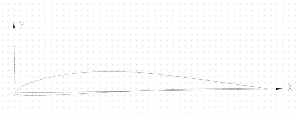
[0035] One available airfoil diagram is shown in figure 1 , the propeller can work under low Reynolds number (Reynolds number less than 10e6). The airfoil data of one available airfoil is given below, see Table 1:

[0036] Table 1 airfoil data table (unit: mm)

[0037]

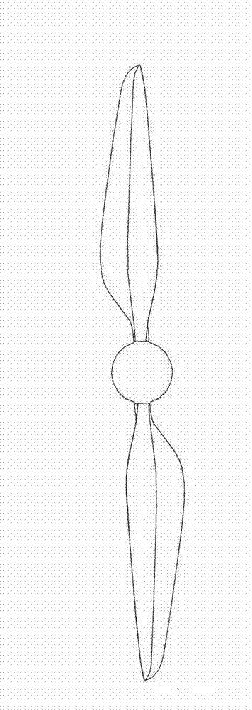
[0038] According to the characterization of the above-mentioned blade shape, the chord length and angle of attack β of the airfoil at different stretch positions are adjusted to obtain a propeller blade shape in the adjacent space. Specifically:

[0039] Chord length (170mm) and angle of attack β (32.52 degrees) at the position of 0.3 span;

[0040] Chord length (150mm) and angle of attack β (26.21 degrees) at the 0.35 span position;

[0041] Chord length (125mm) and angle of attack β (20.50 degrees) at the position of 0.45 span;

[0042] Chord length (104mm) and angle of attack β (17.07 degrees) at the position of 0.6 span;

[0043] Chord length (92mm) and angle of attack β (15.50 degrees) at the 0.7...


PUM

PropertyMeasurementUnit
Chord lengthaaaaaaaaaa

Abstract

A near space propeller comprises propeller blades and propeller hub. Two propeller blades are connected through the propeller hub to form an integral structure; and the propeller blades have the following structure: chord length of 160-180mm and angle of attack beta of 31-34 degree at 0.3 elongation position; chord length of 140-160mm and angle of attack beta of 25-28 degree at 0.35 elongation position; chord length of 115-135mm and angle of attack beta of 18-21 degree at 0.45 elongation position; chord length of 95-110mm and angle of attack beta of 16-18 degree at 0.6 elongation position; chord length of 85-95mm and angle of attack beta of 14-16 degree at 0.7 elongation position; chord length 65-75mm and angle of attack beta of 13-14 degree at 0.75 elongation position; and chord length of 45-55mm and angle of attack beta of 12-13 degree at 0.9 elongation position.

Description


Claims


Application Information

Patent Timeline
Owner CHINA ACAD OF AEROSPACE AERODYNAMICS
Why Eureka
Try Eureka