Cable laying device adopting guiding type control of fixed pulleys

A cable laying and guiding technology, applied in the direction of cable laying equipment, etc., can solve the problems of low work efficiency, heavy workload, time-consuming and laborious, etc., and achieve the effect of simple structure, improved work efficiency and convenient use

Inactive Publication Date: 2013-03-13
JIAXING ELECTRIC POWER BUREAU +1
View PDF4 Cites 8 Cited by
  • Summary
  • Abstract
  • Description
  • Claims
  • Application Information

AI Technical Summary

Problems solved by technology

[0002] The grass-roots units of the power system generally have many infrastructure and technical transformation projects. For relay protection and DC transformation, the workload of laying control ca

Method used


Image

  • Cable laying device adopting guiding type control of fixed pulleys
  • Cable laying device adopting guiding type control of fixed pulleys

Examples


Embodiment

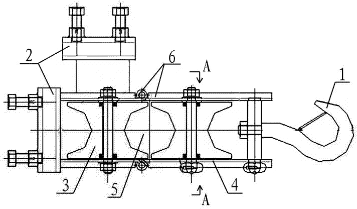
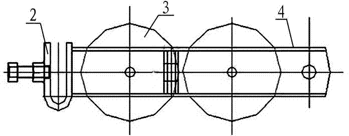
[0013] The cable laying device of the present invention is mainly composed of a hook, a U-shaped bracket, and two nylon king pulleys; in actual use, a U-shaped bracket that changes the direction and fixes the steering and has the effect of increasing the height can also be spared . The U-shaped bracket solves the situation that the original cannot be fixed firmly. After the spare U-shaped bracket is fixed on the general bracket, the direction of the cable can be changed to a certain extent. Wear through the device. The invention improves the fixed bolt, which is not easy to fall off, and adopts double locking buckles to be safer.

[0014] Considering the removal of the cable after the cable laying is completed, we made the device detachable with double locks. When we laid the cable in place, we opened the double locks and opened them to both sides, that is, opened one of the pulleys. The power cable can be removed through a large opening. Since the diameter of the control c...


PUM


Abstract

The invention adopts a cable laying device adopting guiding type control of fixed pulleys. The cable laying device is mainly composed of a hook, a U-shaped fixed frame and two adjacently-installed pulley blocks. The pulleys are fixed on a pulley frame through middle axles of the corresponding pulleys, a cable space for cables to pass through is formed in the middle, one end of the pulley frame is fixedly connected with the U-shaped fixed frame, the hook used for being hung on a cable shaft is fixed at the other end of the pulley frame, a detachable double-locking-catch mechanism is arranged on the pulley frame relative to a position between two pulleys, the double-locking-catch mechanism is formed by locking plates and plug pins, the locking plates can be opened towards two sides to take out the cables, and the plug pins can be used for fixing the locking plates. The cable laying device adopting the guiding type control of fixed pulleys has the advantages of being simple in structure, convenient and reliable to use and capable of reducing cable laying personnel and cable laying time, improving working efficiency and the like.

Description

technical field [0001] The invention relates to a cable laying device controlled by a fixed pulley guide, which is mainly used for laying secondary control cables in power system substations, and is also used for laying cables with a diameter less than 60 mm. Background technique [0002] The grass-roots units of the power system generally have many infrastructure and technical transformation projects. For relay protection and DC transformation, the workload of laying control cables is very large. Due to the tight personnel and construction schedule, a large number of migrant workers are often required to help lay them. Time-consuming and labor-intensive, the work efficiency is low. Contents of the invention [0003] The object of the present invention is to overcome the deficiencies of the prior art, and provide a simple structure, convenient and reliable use, which can reduce the time of cable laying personnel and cable laying, and improve work efficiency by adopting fix...

Claims


Application Information

Patent Timeline
IPC IPC(8): H02G1/06
Inventor 陈全观黄龙飞杨旭风严惟冰支燕炜章寿松沈一辛马志强田春华王阳周程肖金建伟言伟吴晓东
Owner JIAXING ELECTRIC POWER BUREAU
Why Eureka
Try Eureka