Micro-current constant voltage device

A technology of constant voltage device and micro current, which is applied in the direction of circuit device, battery circuit device, measuring device, etc. It can solve problems such as peak voltage generation, charging test safety, battery protection board damage, etc., to improve speed and stability, The effect of small influence on normal operation and simple circuit structure

Active Publication Date: 2015-03-25
GUANGZHOU QINGTIAN INDAL
View PDF4 Cites 0 Cited by
  • Summary
  • Abstract
  • Description
  • Claims
  • Application Information

AI Technical Summary

Problems solved by technology

When the protection switch of the battery is turned off in an abnormal situation, the charging current of the battery is instantly reduced to zero due to the disconnection of the battery cell, and at this time the battery protection board is still connected to the constant current and constant voltage charging circuit through the positive and negative tabs of the battery. connected with each other, the voltage loaded on the battery protection board rises rapidly. Although the constant current and constant voltage charging circuits all have a constant voltage circuit with a constant voltage setting value Vset, the constant voltage circuit will increase when the output voltage Vin of the charging circuit rises to a constant voltage. Start to stabilize the output voltage when the voltage setting value Vset is set, but due to the response time of the constant voltage circuit, the output voltage will still produce a peak voltage due to the rapid rise. The larger the original charging current value, the greater the peak voltage value generated. , especially in the constant current charging state, the peak voltage value is particularly large, which can easily lead to damage to the battery protection board; and, after the protection switch is disconnected, the constant current and constant voltage charging circuit will be empty-loaded, and the constant voltage state cannot be maintained. Therefore, the current and constant voltage charging condition is canceled, which also affects the test work, causing potential safety hazards in the charging test

Method used


Image

  • Micro-current constant voltage device
  • Micro-current constant voltage device
  • Micro-current constant voltage device

Examples


Embodiment Construction

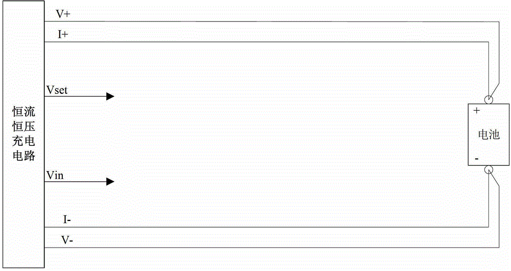
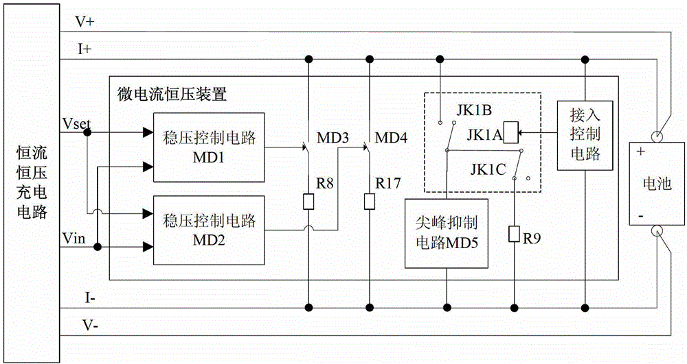
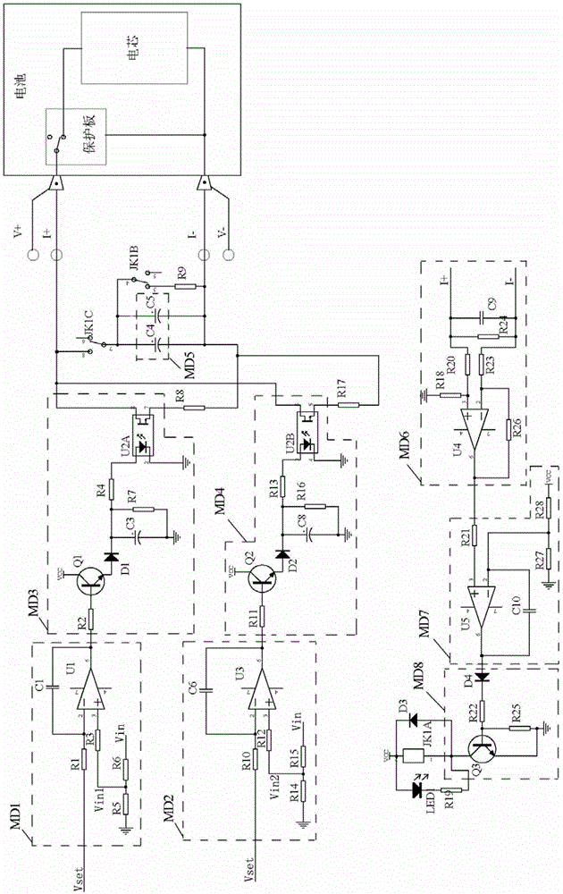
[0019] like figure 2 and image 3 As shown, the micro-current and constant-voltage device of the present invention is applied in a constant-current and constant-voltage charging circuit, and the device includes a two-stage voltage stabilizing circuit, a spike suppression circuit MD5, a switching relay, an access control circuit and a power resistor R9.

[0020] The first stage voltage stabilizing circuit of the present invention is made up of voltage stabilizing control circuit MD1, electronic switch MD3 and shunt resistor R8, electronic switch MD3 and shunt resistor R8 are connected in series and the series branch is connected to the output terminal positive of the constant current and constant voltage charging circuit. Between the pole I+ and the negative pole I- of the output terminal, the voltage stabilizing control circuit MD1 has a proportional coefficient less than 1, and the output terminal of the voltage stabilizing control circuit MD1 is connected to the control ter...


PUM


Abstract

The invention discloses a micro-current constant voltage device. The device is applied to a constant current constant voltage charging circuit. The device comprises a peak suppression circuit and a voltage stabilizing circuit, wherein one or more capacitors are connected in parallel to form the peak suppression circuit, the peak suppression circuit is connected between the cathode and the anode of the output end of the constant current constant voltage charging circuit, the voltage stabilizing circuit consists of a voltage stabilizing control circuit, an electronic switch and a shunt resistor, the electronic switch and the shunt resistor are connected in series and are connected between the cathode and the anode of the output end of the constant current constant voltage charging circuit, the voltage stabilizing control circuit has a proportionality coefficient of less than one, the output end of the voltage stabilizing control circuit is connected to a control end of the electronic switch, the voltage stabilizing control circuit is based whether the product of the output voltage value of the constant current constant voltage charging circuit and the proportionality coefficient is larger than the constant voltage setting value of the constant current constant voltage charging circuit, and the electronic switch is controlled to be connected or disconnected. By the aid of the device, the peak voltage output by the constant current constant voltage charging circuit can be suppressed and the voltage stabilizing output of the constant current constant voltage charging circuit can be maintained during the no loading.

Description

technical field [0001] The invention relates to a voltage stabilizing protection device, in particular to a micro-current constant-voltage device applied to a constant-current and constant-voltage charging circuit. Background technique [0002] Rechargeable batteries generally use a battery protection board to protect their cells from overcharging, overdischarging and short circuit protection. The protection switch is the executive device for the battery protection board to protect the battery cells. The battery protection board detects whether the battery is abnormal, and controls the connection between the battery cell and the positive and negative tabs of the battery through the protection switch. Under normal circumstances, the protection switch is closed, the battery cell and the positive and negative poles of the battery are connected, and the battery can be charged and discharged; when an abnormal situation occurs, the protection switch is disconnected, and the positi...

Claims


Application Information

Patent Timeline
Patent Type & Authority Patents(China)
IPC IPC(8): H02J7/00G01R31/36
Inventor 黄维佳曾志永刘春华
Owner GUANGZHOU QINGTIAN INDAL
Why Eureka
Try Eureka