Supercharge Your Innovation With Domain-Expert AI Agents!

A disc-shaped asynchronous magnetic coupling and speed regulation method

A magnetic coupling and asynchronous technology, applied in the direction of electrical components, electromechanical devices, electromechanical transmission devices, etc., can solve the problems of reduced assembly difficulty, high assembly difficulty, and reduced neutral requirements, so as to reduce friction and wear, Improved transmission efficiency and compact structure

Inactive Publication Date: 2015-08-26
JIANGSU UNIV
View PDF7 Cites 0 Cited by
  • Summary
  • Abstract
  • Description
  • Claims
  • Application Information

AI Technical Summary

Problems solved by technology

[0004] In the patent application number CN201010149939.6, a magnetic gear high-temperature-resistant high-speed magnetic pump is disclosed, including: an outer rotor, a middle rotor, an inner rotor, a magnetic adjustment device, and a spacer sleeve. The speed of the pump, in which the middle rotor is used as the inner rotor of the magnetic gear and the outer rotor of the magnetic coupling, makes the structure more compact, effectively reduces friction and wear, and improves the transmission efficiency, but there is a neutrality in this patent High requirements, difficult assembly, and large radial size; the present invention is a disk-shaped asynchronous magnetic coupling based on axial magnetic field modulation magnetic gear, which adopts axial magnetic field modulation magnetic gear and disk asynchronous magnetic coupling The combination of shafts and shafts can also meet the requirements of variable speed transmission, and the disc structure reduces the neutral requirements of the device and reduces the difficulty of assembly, so it is also significantly different from the above patents.

Method used


Image

  • A disc-shaped asynchronous magnetic coupling and speed regulation method
  • A disc-shaped asynchronous magnetic coupling and speed regulation method
  • A disc-shaped asynchronous magnetic coupling and speed regulation method

Examples


Embodiment Construction

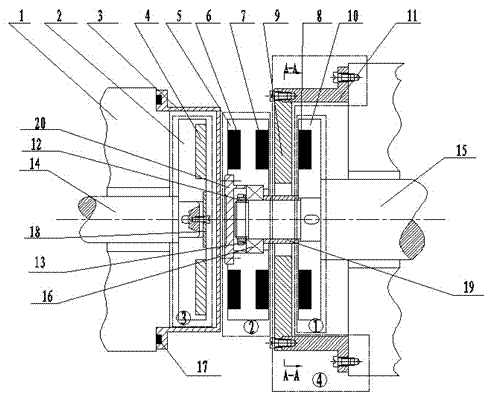
[0018] Combine below figure 1 The implementation of the present invention is described in detail, the general structure of the present invention is as follows figure 1 As shown, the device includes: driving disk assembly ①, intermediate disk assembly ②, driven disk assembly ③, magnetic adjustment device ④ and spacer 3; driving disk assembly ① consists of driving disk base 10, first permanent magnet 8, the intermediate disk assembly ② is composed of the intermediate disk base 5, the third permanent magnet 6, and the second permanent magnet 7, and the driven disk assembly ③ is composed of the driven disk base 2, the guide bar 4, and the conductor end ring 24. Magnetic adjustment device ④ is composed of magnetic adjustment pole piece 9 and fixed sleeve 11. It is characterized by: driven disk assembly ③, spacer sleeve 3, intermediate disk assembly ②, magnetic adjustment device ④ and driving disk assembly ① from left to The right is arranged axially along the driven shaft or the d...


PUM


Abstract

The invention relates to the technical field of mechanical engineering transmission, in particular to a disc-shaped asynchronous magnetic coupling and a speed adjustment method. The coupling comprises a driving disc assembly, a middle disc assembly, a driven disc assembly and a magnetism adjustment device. The driving disc assembly, the magnetism adjustment device and the middle disc assembly form an axial magnetic field modulation magnetic gear, and the middle disc assembly and the driven disc assembly further form a disc type asynchronous magnetic coupling simultaneously. According to the disc-shaped asynchronous magnetic coupling and the speed adjustment method, when the drive shaft input rotation speed is fixed, the speed is changed through the axial magnetic field modulation magnetic gear, and different rotation speeds and torques of a driven shaft are output through the disc type asynchronous magnetic coupling. Not only characteristics of magnetic gear variable-speed transmission are provided, but also advantages of good starting performances and not demagnetization in high-temperature working conditions of the disc type asynchronous magnetic coupling are provided. The coupling and the method can be used in industries for conveying high-temperature and toxic media and can achieve non-leakage conveying effects, and application ranges of magnetic couplings are further expanded.

Description

technical field [0001] The invention relates to the technical field of mechanical engineering transmission, in particular to a disk-shaped asynchronous magnetic coupling based on an axial magnetic field modulation magnetic gear, which can realize the output of different speeds and torques, and is suitable for motors in oil refining, chemical industry, coal and other industries The transmission system between the load and other devices. Background technique [0002] Magnetic transmission is a new type of transmission technology, which uses the magnetic force generated by permanent magnet materials or electromagnets to realize the transmission of force or torque. Compared with mechanical transmission, magnetic transmission has outstanding advantages, such as: reducing friction, improving efficiency, Vibration isolation, automatic overload protection, physical separation of input shaft and output shaft, etc. [0003] With the continuous deepening of the research on magnetic tr...

Claims


Application Information

Patent Timeline
Patent Type & Authority Patents(China)
IPC IPC(8): H02K51/00
Inventor 杨超君徐燕飞周曰华
Owner JIANGSU UNIV
Features
  • R&D
  • Intellectual Property
  • Life Sciences
  • Materials
  • Tech Scout
  • Unparalleled Data Quality
  • Higher Quality Content
  • 60% Fewer Hallucinations
Learn More