Transistor ladder network for driving a light emitting diode series string

A technology of light-emitting diodes and transistors, which is applied in the field of transistor ladder networks used to drive series strings of light-emitting diodes, and can solve problems such as harmonic distortion of LED strings

Inactive Publication Date: 2013-03-13
3M INNOVATIVE PROPERTIES CO
View PDF12 Cites 3 Cited by
  • Summary
  • Abstract
  • Description
  • Claims
  • Application Information

AI Technical Summary

Problems solved by technology

However, such directly driven LED strings have a large amount of undesired harmonic distortion

Method used


Image

  • Transistor ladder network for driving a light emitting diode series string
  • Transistor ladder network for driving a light emitting diode series string
  • Transistor ladder network for driving a light emitting diode series string

Examples


Embodiment Construction

[0012] Embodiments of the LED drive circuit allow driving multiple LEDs in series in AC line applications with minimal harmonic distortion in the drive current and near unity power factor. The circuit also allows direct dimming as well as color changes via dimmer circuits (eg, conventional TRIAC dimmers). In addition, the circuit is protected against line voltage surges and is relatively insensitive to brown-out operation.

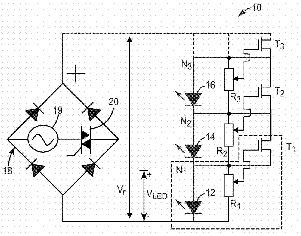
[0013] figure 1 is a schematic diagram of a FET circuit 10 for driving a series string of LEDs. The circuit 10 comprises a series of three (m=3) segments N connected in series 1 , N 2 and N 3 . Each segment controls N m LED junction. The first section includes N 1 LED junction 12 (shown as a diode), resistor R 1 and transistor T 1 . The second section includes N 2 LED junction 14 (shown as a diode), resistor R 2 and transistor T 2 . The third section includes N 3 LED junction 16 (shown as a diode), resistor R 3 and transistor T 3 . In e...


PUM


Abstract

Ladder network circuits for controlling operation of a string of light emitting diodes (LEDS). The circuits include a number of sections connected in series. Each section includes one or more LED junctions, a variable resistive element coupled to the LED section, and a switch coupled to the variable resistive element and the LED section for controlling activation of the LED. The sections can include a transistor coupled between the switch and variable resistive element. The series of sections are connected to an AC power source, rectifier, and dimmer circuit. When receiving power from the power source, the sections activate the LEDs in sequence throughout the series of the sections. The dimmer circuit controls activation of a selection of one or more of the sections in order to activate in sequence the LEDs in only the selected sections, providing for both dimming and color control of the LEDs.

Description

Background technique [0001] A string of multiple light emitting diodes (LEDs) connected in series can be AC ​​driven directly from a standard AC line power supply. However, such directly driven LED strings have a large amount of undesired harmonic distortion. Additionally, dimming capability is included. Alternatively, the LED string can be DC driven, which requires conversion electronics to convert standard AC power to DC current. Therefore, modifications or improvements are needed to allow sufficient current flow for low drive voltages with minimal harmonic distortion and near unity power factor to allow for implementations that allow dimming capability (especially when LED lamps replace incandescent or fluorescent lamps) Time). Contents of the invention [0002] According to the invention, a first circuit for controlling the operation of a string of LEDs comprises a plurality of segments connected in series and configured to be connected to a power source. Each segmen...

Claims


Application Information

Patent Timeline
Patent Type & Authority Applications(China)
IPC IPC(8): H05B37/02H05B44/00
CPCH05B33/0845H05B33/0809H05B33/083Y02B20/341H05B45/48Y02B20/30H05B45/20H05B45/31H05B45/10
Inventor 马丁·J·福斯
Owner 3M INNOVATIVE PROPERTIES CO
Why Eureka
Try Eureka