Vibrating-dewatering screen driving mechanism

A driving mechanism and dewatering screen technology, applied in engine components, engine seals, mechanical equipment, etc., can solve the problems of high manufacturing cost, complex manufacturing process, and shorten the service life of equipment, and reduce abnormal wear conditions and manufacturing processes. Good performance and improved sealing performance

Inactive Publication Date: 2013-03-20
XUZHOU HAILUN AGRI TECH
View PDF0 Cites 2 Cited by
  • Summary
  • Abstract
  • Description
  • Claims
  • Application Information

AI Technical Summary

Problems solved by technology

[0002] At present, the driving mechanism of the vibrating dewatering screen generally includes a pair of bearing seats symmetrically installed and fixed on the screen basket, and the eccentric part of the crankshaft is installed on the bearing seats through sliding bearings. In addition, the working environment of the vibrating screen is generally harsh, and the bearing wear is serious, resulting in a low service life of the equipment. In addition, in the existing vibrating screen drive mechanism, the eccentric shaft that transmits power is generally an integral structure, and there are manufacturing The process is complicated and the manufacturing cost is relatively high. At the same time, due to the complex force condition of the eccentric part of the drive shaft, the wear is relatively serious. Once the wear of the eccentric part exceeds a certain limit, the entire drive shaft has to be scrapped. Therefore, further Reduce the service life of the equipment and increase the cost of the equipment

Method used


Image

  • Vibrating-dewatering screen driving mechanism

Examples


Embodiment Construction

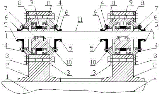
[0008] A vibrating dehydration screen driving mechanism, including a screen frame 1, a bearing seat 2, a bearing gland 3, an annular pressure plate 4, a pagoda-shaped rubber sleeve 5, a spring pull ring 6, a key 7, a bearing 8, a spacer sleeve 9, and an eccentric sleeve 10. Transmission shaft 11, two identical bearing housings 2 are symmetrically installed and fixed on the upper edge of the screen frame 1, and an eccentric sleeve 10 is installed and fixed through two bearings 8 in the inner hole of each bearing housing 2. A spacer 9 is installed between the two bearings 8 on the outer circle of each eccentric sleeve 10, and a transmission shaft 11 is installed and fixed in the inner holes of the two eccentric sleeves 10 through a key 7. The eccentric direction of the two eccentric sleeves 10 Consistent, install and fix a bearing gland 3 at the ports on both sides of each bearing seat 2. Annular pressing plate 4 and screw are fixed a pagoda-shaped rubber sleeve 5, and a spring ...


PUM


Abstract

The invention discloses a vibrating-dewatering screen driving mechanism. Two same bearing pedestals are symmetrically and fixedly arranged at an edge opening at the upper part of a screen frame; an eccentric sleeve is fixedly arranged in an inner hole of each bearing pedestal through two bearings; an isolating sleeve is arranged between the two bearings on the outer circle of each eccentric sleeve; a transmission shaft is fixedly arranged in inner holes of the two eccentric sleeves through keys; a bearing pedestal gland is fixedly arranged at the port at each of two ends of each bearing pedestal; a tower-shaped rubber sleeve is fixed at the outer edge opening of each bearing gland through a ring-shaped press plate and a bolt; and a spring pull ring is sleeved on the outer circle of the small head of each tower-shaped rubber sleeve. By the vibrating-dewatering screen driving mechanism, the service life of the bearings and the overall service life of equipment can be prolonged; and furthermore, the vibrating-dewatering screen driving mechanism has the advantages of simple structure, relatively high manufacturing technique, relatively low manufacturing cost and long service life.

Description

technical field [0001] The invention relates to coal preparation equipment, in particular to a vibrating dewatering screen, in particular to a driving mechanism for vibration of the vibrating dewatering screen, and belongs to the technical field of vibrating dewatering screens. Background technique [0002] At present, the driving mechanism of the vibrating dewatering screen generally includes a pair of bearing seats symmetrically installed and fixed on the screen basket, and the eccentric part of the crankshaft is installed on the bearing seats through sliding bearings. In addition, the working environment of the vibrating screen is generally harsh, and the bearing wear is serious, resulting in a low service life of the equipment. In addition, in the existing vibrating screen drive mechanism, the eccentric shaft that transmits power is generally an integral structure, and there are manufacturing The process is complicated and the manufacturing cost is relatively high. At th...

Claims


Application Information

Patent Timeline
Patent Type & Authority Applications(China)
IPC IPC(8): B01D33/03F16J15/52
Inventor 陈亮
Owner XUZHOU HAILUN AGRI TECH
Why Eureka
Try Eureka