Cutting punch

A technology of punching machine and feeding die, which is applied in the field of material cutting punching machine, can solve problems such as prone to inclined surfaces, poor fixation, and affecting use, and achieve the effects of improving work efficiency, saving materials, and reducing work efficiency

Inactive Publication Date: 2013-03-20
吕彬
View PDF10 Cites 2 Cited by
  • Summary
  • Abstract
  • Description
  • Claims
  • Application Information

AI Technical Summary

Problems solved by technology

[0002] When the profile cutting punch is cutting, the cutting surface of the knife plate to the profile is prone to be inclined. The impact causes the profile to deviate, so the cutting surface is an inclined plane, which affects the use and needs to be improved
[0003] For this reason, many people conduct research on this to solve this problem, but there is no relevant equipment on the market to solve this problem

Method used


Image

  • Cutting punch
  • Cutting punch

Examples


Embodiment Construction

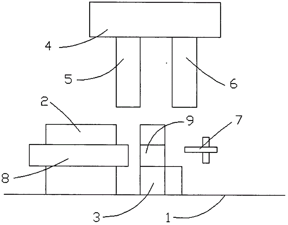
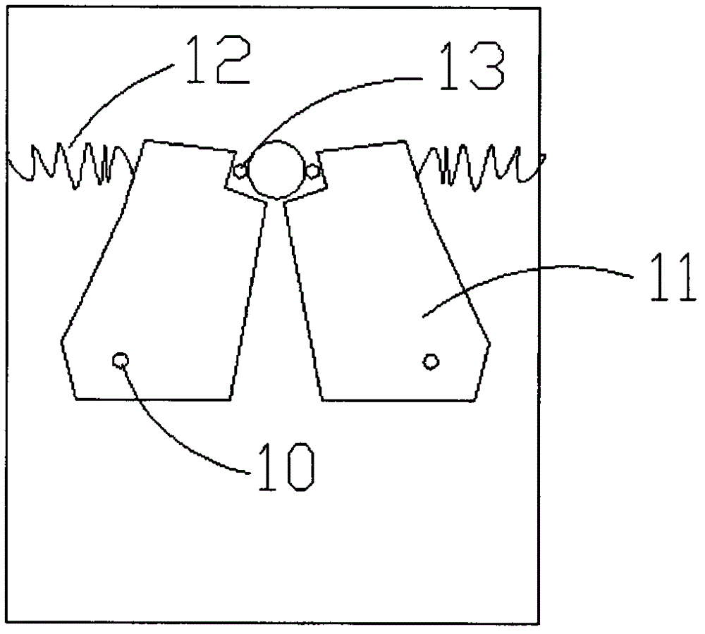
[0023] Such as figure 1 and figure 2 As shown, the present invention relates to a material cutting punch, comprising a base plate 1, characterized in that: a feeding die 2 and a support die 3 are arranged on the base plate 1, and a blanking die is provided above the feed die 2 and the support die 3 mechanism, a clamping mechanism is provided on the support mold 3, and the blanking mechanism includes a knife plate 5 and a blanking plate 6 arranged on the same fixed plate 4, and a limit rod 7 is provided on one side of the support mold 3.

[0024] It is further provided that the distance between the supporting mold 3 and the feeding mold 2 is the width of the knife plate 5 .

[0025] It is further provided that a feed channel 8 is formed on the feed mold 2 .

[0026] It is further provided that a supporting channel 9 is formed on the supporting mold 3 , and the width of the supporting channel 9 is less than or equal to the width of the knife plate 5 .

[0027] It is further ...


PUM


Abstract

The invention discloses a cutting punch, which comprises a bottom plate. A feeding die and a support die are arranged on the bottom plate. A blanking mechanism is arranged above the feeding die and the support die. A clamping mechanism is arranged on the support die. The blanking mechanism comprises a cutting plate and a blanking plate, which are arranged on the same fixing plate. A limiting rod is arranged on one side of the support die. The cutting punch is simple and delicate in structure, an obtained product has a perpendicular cut surface, and simultaneouslymeanwhile, the working efficiency is greatly improved.

Description

technical field [0001] The invention relates to a material cutting punch. Background technique [0002] When the profile cutting punch is cutting, the cutting surface of the profile is prone to be inclined by the knife plate. The main reason is that the profile is not fixed well during the feeding process, and the knife plate is in the downward cutting movement. The impact causes the profile to deviate. Therefore, the cutting surface is an inclined plane, which affects the use and needs to be improved. [0003] For this reason, a lot of people are researched to this, to solve this problem, but also do not have relevant equipment to solve this problem on the market at present. [0004] It can be seen from the above that it is imminent to solve these problems! [0005] In view of this, the present inventor has done in-depth research, and by virtue of years of experience and practice in related industries, has designed a cutting punch, which can solve the deficiencies in the ...

Claims


Application Information

Patent Timeline
IPC IPC(8): B21D28/02
Inventor 吕彬盛伯康
Owner 吕彬
Why Eureka
Try Eureka