Adjustable middle support device for machining overlength shaft

A technology of adjustment device and intermediate support, applied in metal processing equipment, tool clamps, manufacturing tools, etc., can solve the problems of not meeting satisfactory processing requirements, unable to fundamentally eliminate deflection, and coaxiality not meeting the requirements, etc. The method is simple and lightweight, eliminates the impact of shock, and has the effect of light structure

Active Publication Date: 2015-01-14
CSSC HUANGPU WENCHONG SHIPBUILDING COMPANY
View PDF6 Cites 0 Cited by
  • Summary
  • Abstract
  • Description
  • Claims
  • Application Information

AI Technical Summary

Problems solved by technology

Such a long boring bar will inevitably produce deflection when both ends are fixed, so the original set of processing equipment is equipped with two intermediate bearings. By adjusting these two intermediate bearings to eliminate the deflection of the boring bar, it still cannot achieve satisfactory processing Requirements, mainly because the coaxiality after boring does not meet the requirements
After analysis, it is found that after the boring bar is installed, the deflection direction of the boring bar is not unidirectional, mainly because in addition to supporting bearing seats at both ends of the boring bar, it is also equipped with feed gear boxes, reduction gear boxes and other equipment In this way, the deflection of the boring bar is not simply the deflection caused by gravity. The multi-point rigid support can generate deflection in any direction, and the detection of this direction is complicated and the adjustment and correction are also very complicated.
The rigid intermediate bearing adjustment adopted by the original device cannot fundamentally eliminate the deflection that may occur in any direction, because it is a rigid fulcrum itself, which is an added rigid constraint for the boring bar, so it will only make the boring The deflection deformation of the rod is more complicated and cannot be eliminated

Method used


Image

  • Adjustable middle support device for machining overlength shaft
  • Adjustable middle support device for machining overlength shaft
  • Adjustable middle support device for machining overlength shaft

Examples


Embodiment Construction

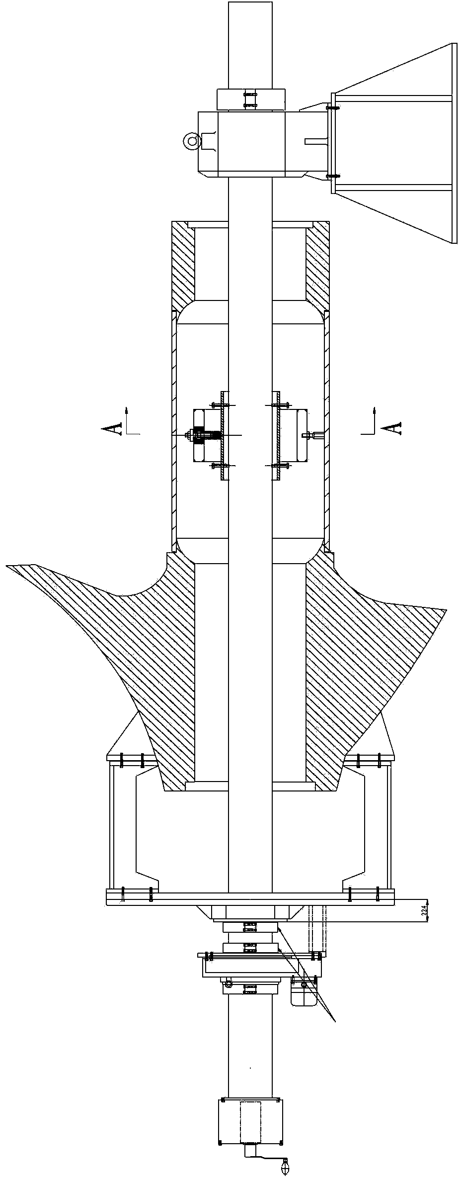
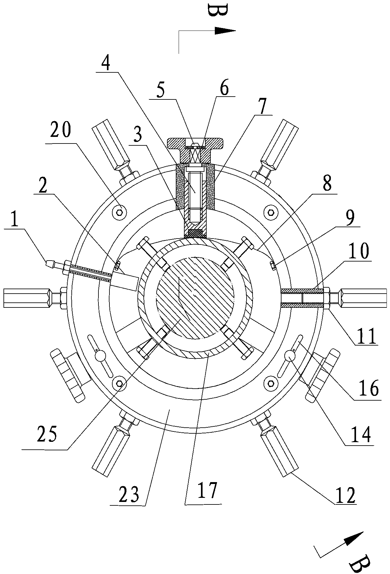
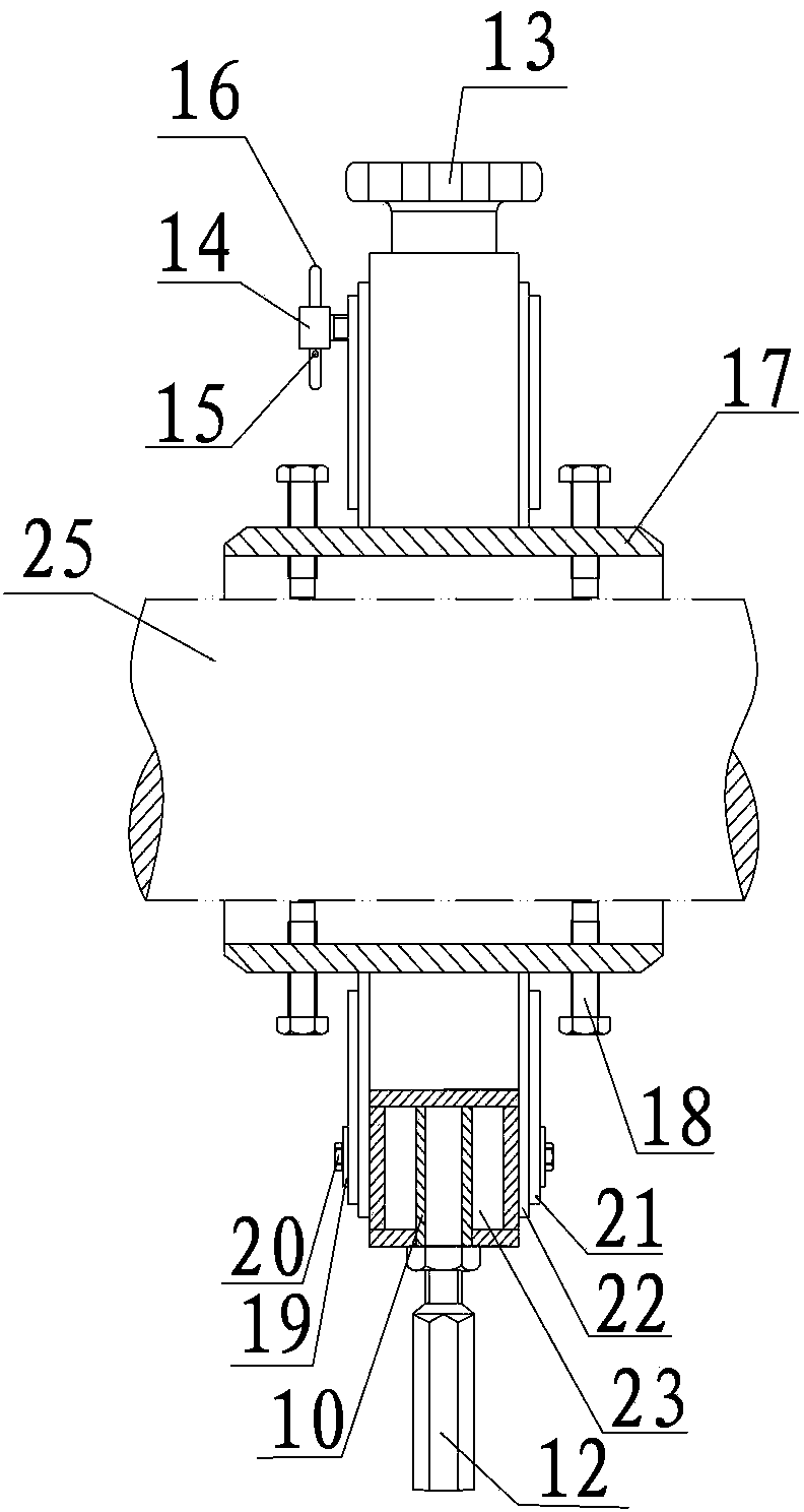
[0024] Attached below Figure 1-7 An embodiment of the present invention is described.

[0025] The adjustable intermediate support device for ultra-long axis processing has a transition sleeve 17 and a support frame 23. The transition sleeve 17 is radially provided with a transition sleeve adjustment device that can adjust the distance between the transition sleeve 17 and the boring bar 25. The support The frame 23 is a hollow circular sleeve and is set on the transition sleeve 17, and the two ends of the support frame 23 are sealed with the transition sleeve 17. The support frame 23 is radially symmetrically provided with a support for adjusting the distance between the support frame 23 and the transition sleeve 17. Frame adjustment device I and the support frame adjustment device II between the adjustable support frame 23 and the inner hole wall of the stern tube. The cavity of the support frame 23 is provided with a rubber hose 2, and one end of the rubber hose 2 is in con...


PUM


Abstract

The invention provides an adjustable middle support device for machining an overlength shaft. The adjustable middle support device comprises a transition sleeve and a support frame, wherein the transition sleeve is radially provided with a transition sleeve adjusting device capable of adjusting a distance between the transition sleeve and a boring rod, the support frame is a hollow circular sleeve and is sleeved on the transition sleeve, two end parts of the support frame are in airtight connection with the transition sleeve, the support frame is radially and symmetrically provided with a support frame adjusting device I capable of adjusting the distance between the support frame and the transition sleeve and a support frame adjusting device II capable of adjusting the supporting frame and a hole wall inside a stern shaft tube, a cavity of the support frame is internally provided with a rubber hose, one end of the rubber hose is in contact with the excircle of the transition sleeve, the other end of the rubber hose is connected with an outlet end of an oil filling nozzle which is fixedly arranged inside the cavity of the support frame, and the top end of the oil filling nozzle extends out of the support frame. The adjustable middle support device disclosed by the invention can be used for not only supporting the long boring rod but also guaranteeing the coaxiality in boring a long shaft hole, and has a higher practical value.

Description

technical field [0001] The invention belongs to the technical field of machining, and in particular relates to an adjustable intermediate support device for ultra-long axis machining. Background technique [0002] The length of the stern tube of a 76,000-ton bulk carrier is more than 3 meters, and the inner hole needs to be bored. The accuracy of the inner hole of the stern tube is related to the installation of the propeller shaft, so it is very important. The roundness, cylindricity and coaxiality of the bored hole must meet the relevant process requirements. Existing Korean long-axis machining equipment, the length of the boring bar has reached more than 8 meters, while the diameter of the boring bar is only 0.22 meters. Such a long boring bar will inevitably produce deflection when both ends are fixed, so the original set of processing equipment is equipped with two intermediate bearings. By adjusting these two intermediate bearings to eliminate the deflection of the b...

Claims


Application Information

Patent Timeline
Patent Type & Authority Patents(China)
IPC IPC(8): B23B29/14B23B29/02B23B41/02
Inventor 陈遵清周学志
Owner CSSC HUANGPU WENCHONG SHIPBUILDING COMPANY
Why Eureka
Try Eureka