
Mold press plate

A technology of mold pressing plate and pressing plate, which is applied in the direction of forming tools, manufacturing tools, metal processing machinery parts, etc., can solve the problems of inconvenient use of pressing plate, increased number of parts, easy loss, etc., achieve a reasonable and practical overall structure, reduce processing steps, The effect of convenient production and assembly

Active Publication Date: 2013-03-20
朱华丰
View PDF9 Cites 4 Cited by
  • Summary
  • Abstract
  • Description
  • Claims
  • Application Information

AI Technical Summary

Problems solved by technology

Its shortcoming is that it is necessary to use gussets to connect the upper and lower pads and fasten them to the pressure plate, resulting in more parts and inconvenient installation and connection. Moreover, the connection strength of the gusset is limited, which makes it inconvenient to use the pressure plate
After adopting the above structure, on the one hand, the upper block, the lower block, and the main body of the pressing plate can be connected into one body to prevent the parts from being scattered during use; on the other hand, the mold of the original connecting sleeve is also omitted, so that The manufacturing cost is lower; however, there is still a fly in the ointment in its improvement: the hollow connecting body passes through the lower through hole and the through hole and is disassembled and connected with the limiter, the parts can be further reduced, easy to be lost, and the assembly and use are not fast enough Convenience, need to further improve the design

Method used


Image

  • Mold press plate
  • Mold press plate
  • Mold press plate

Examples


Embodiment Construction

[0021] The present invention will be further described in detail below in conjunction with the accompanying drawings and embodiments.

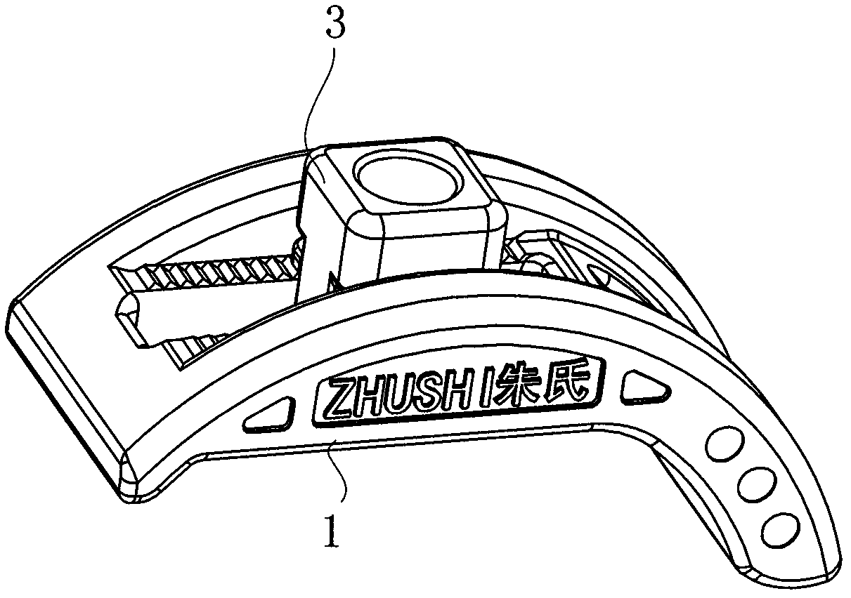
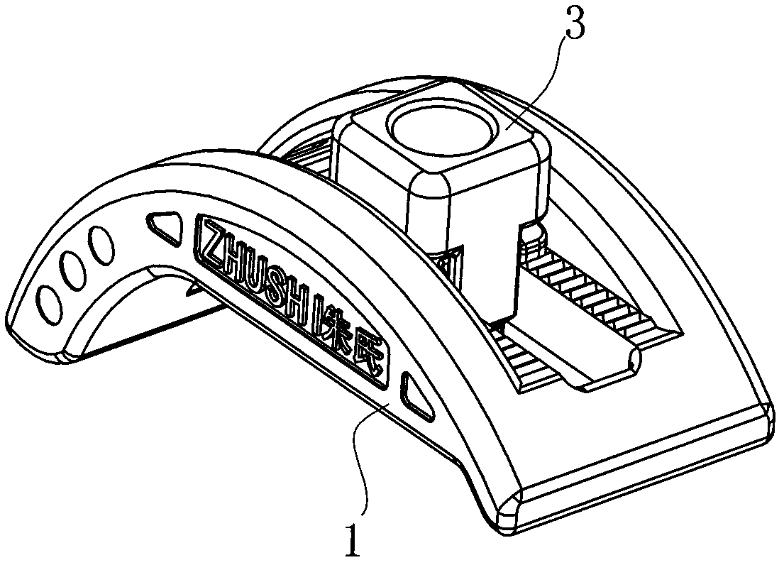
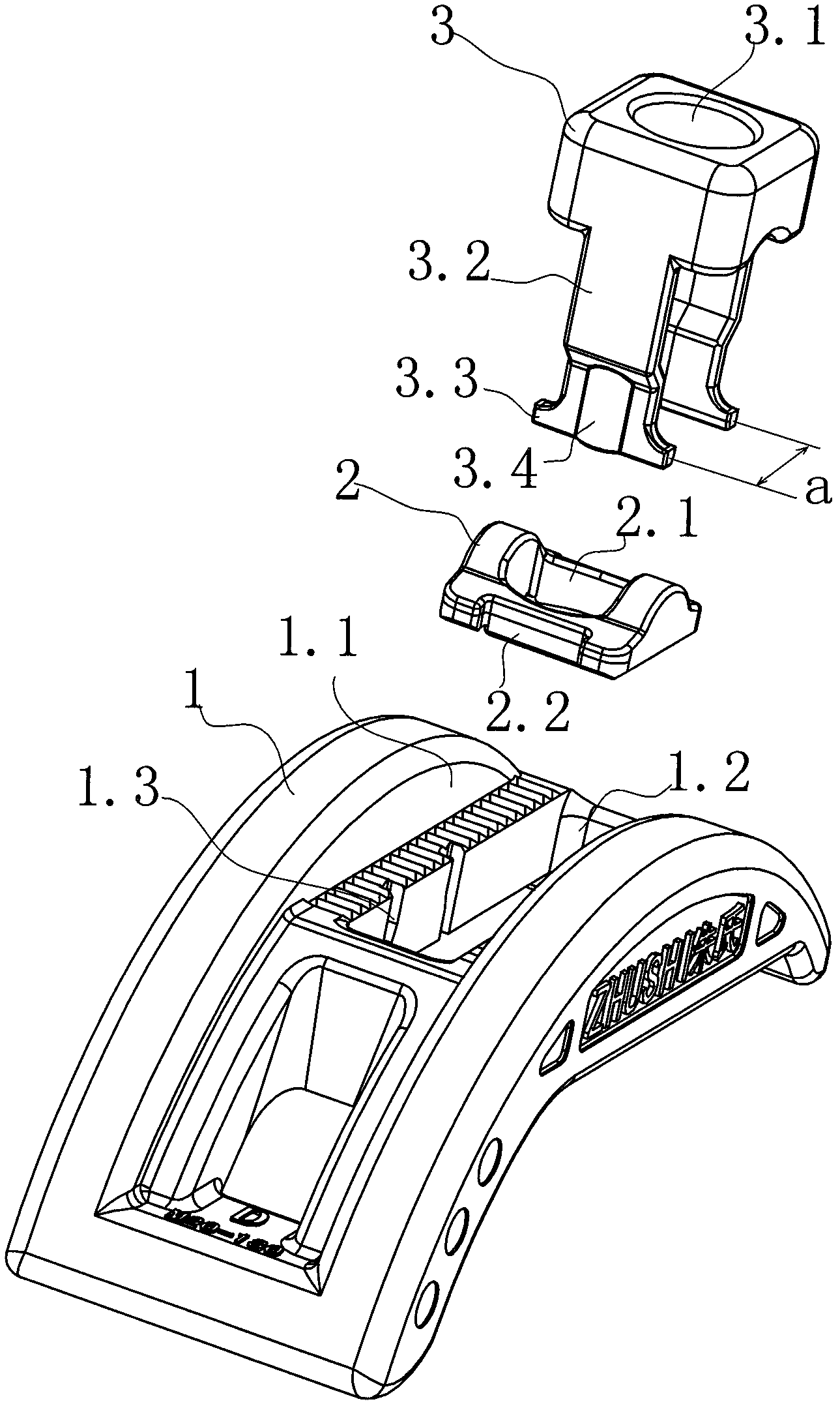
[0022] Such as Figure 1-6 Shown is a mold platen, which includes a platen main body 1, a lower cushion block 2 and an upper cushion block 3 arranged on the lower cushion block, wherein a longitudinal groove 1.1 is provided in the middle of the upper surface of the platen main body 1, in which The bottom of the groove 1.1 is provided with a longitudinal through hole 1.2, and the upper block 3 and the lower block 2 are fitted with an arc surface, and both of them are located in the longitudinal groove 1.1, and are placed in the longitudinal On the bottom surface of the groove 1.1, an upper through hole 3.1 and a lower through hole 2.1 corresponding to the position of the above-mentioned through hole 1.2 and allowing the screw to pass through are provided in the middle of the upper pad 3 and the lower pad 2. These are compared with The mold pla...


PUM


Abstract

A mold press plate comprises a press plate body, a lower cushion block and an upper cushion block arranged on the lower cushion block, wherein a longitudinal groove is formed in the upper surface of the press plate body, a longitudinal through hole is formed in the bottom of the longitudinal groove, the upper cushion block and the lower cushion block are in cambered-surface fit with each other and are arranged in the bottom face of the longitudinal groove, and meanwhile an upper through hole and a lower through hole are formed in the middles of the upper cushion block and the lower cushion block. The upper through hole and the lower through hole correspond to the position of the through hole for a screw to penetrate through. The mold press plate is characterized in that a downwards extending part is arranged on at least one of the front side portion and the back side portion of the upper cushion block, a clamping stop part is arranged at the lower end of the extending part, correspondingly, guide grooves are formed in side walls of two sides of the longitudinal through hole and are in sliding fit with the extending part, and the clamping stop part of the extending part is limited on the bottom face of the press plate body through elastic deformation of the extending part. The mold press plate is simple and reasonable in structure, convenient to assemble and use, quick in assembly and use, and low in cost.

Description

technical field [0001] The invention relates to the technical field of a mold pressing plate. Background technique [0002] Mold platen is a common fixture in the mechanical processing industry. The traditional flat mold platen is gradually replaced by mold platens with various structures on the market because of its pads are prone to drop and loss. [0003] Such as the Chinese utility model patent No. 99206225.X, which includes a pressing plate with a long groove in the longitudinal direction and a pair of upper and lower pads on the string for pressing screws. It is characterized in that the pressing plate is arched, and on its back There is a row of finely distributed racks along both sides of the long groove, the tooth-shaped fit between the lower liner and the pressure plate, and the arc-shaped fit between the upper and lower liners. Such a pressure plate group has a simple structure. The screw is matched with a pair of arc-shaped upper and lower gaskets and the serrat...

Claims


Application Information

Patent Timeline
Patent Type & Authority Applications(China)
IPC IPC(8): B23Q3/06
CPCB25B1/00B25B5/105B23Q3/06B21D37/00
Inventor 朱华丰
Owner 朱华丰
Learn More