Automobile seat slide
A car seat slide rail and slide rail technology, which is applied to movable seats and other directions, can solve the problems of affecting riding comfort, many slide rail parts, and cumbersome assembly, and achieves simple structure, few parts, and improved comfort Effect
- Summary
- Abstract
- Description
- Claims
- Application Information
AI Technical Summary
Problems solved by technology
Method used
Image

Examples
Embodiment 1
[0026] This embodiment relates to a car seat slide rail.
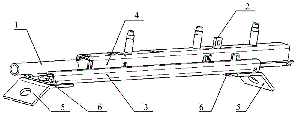
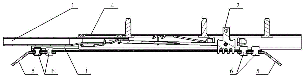
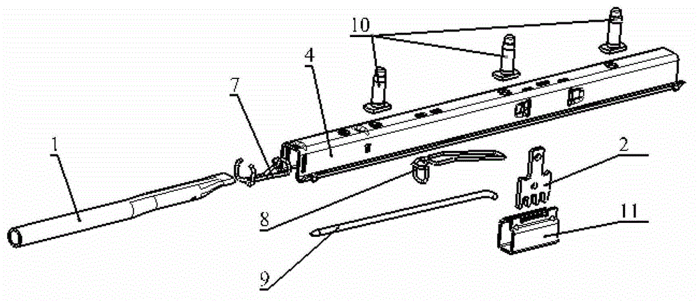
[0027] like figure 1 and figure 2 The car seat sliding rail shown includes: an unlocking lever 1; a sliding rail 3 connected with the body and always in a static state with a wall thickness of 1.6mm; The upper slide rail 4; the locking plate 2 that is fixed with the upper slide rail 4 and realizes the locking and unlocking functions by moving up and down; the slide rail pin 5 that connects the slide rail 3 and the vehicle body; connects the slide rail pin 5 and the lower rail 3, and at the same time limit the rivets 6 of the front and rear limit positions of the upper rail 4; reset the unlocking spring 7 of the unlocking lever 1; keep the unlocking lever 1 in the locked state all the time, and simultaneously start The locking spring 8 to the leverage of the connecting rod; the connecting rod 9 that connects the unlocking lever 1 and the locking plate 2 and realizes the linkage between the unlocking lever 1 and the l...
Embodiment 2
[0029] This embodiment relates to a car seat slide rail.
[0030] like figure 1 and figure 2 The car seat sliding rail shown includes: an unlocking lever 1; a sliding rail 3 connected with the body and always in a static state with a wall thickness of 1.0mm; The upper slide rail 4; the locking plate 2 that is fixed with the upper slide rail 4 and realizes the locking and unlocking functions by moving up and down; the slide rail pin 5 that connects the slide rail 3 and the vehicle body; connects the slide rail pin 5 and the lower rail 3, and at the same time limit the rivets 6 of the front and rear limit positions of the upper rail 4; reset the unlocking spring 7 of the unlocking lever 1; keep the unlocking lever 1 in the locked state all the time, and simultaneously start The locking spring 8 to the leverage of the connecting rod; the connecting rod 9 that connects the unlocking lever 1 and the locking plate 2 and realizes the linkage between the unlocking lever 1 and the l...
Embodiment 3
[0032] This embodiment relates to a car seat slide rail.
[0033] like figure 1 and figure 2 The car seat sliding rail shown includes: an unlocking lever 1; a sliding rail 3 connected to the body and always in a static state with a wall thickness of 3.0mm; The upper slide rail 4; the locking plate 2 that is fixed with the upper slide rail 4 and realizes the locking and unlocking functions by moving up and down; the slide rail pin 5 that connects the slide rail 3 and the vehicle body; connects the slide rail pin 5 and the lower rail 3, and at the same time limit the rivets 6 of the front and rear limit positions of the upper rail 4; reset the unlocking spring 7 of the unlocking lever 1; keep the unlocking lever 1 in the locked state all the time, and simultaneously start The locking spring 8 to the leverage of the connecting rod; the connecting rod 9 that connects the unlocking lever 1 and the locking plate 2 and realizes the linkage between the unlocking lever 1 and the loc...
PUM
| Property | Measurement | Unit |
|---|---|---|
| Wall thickness | aaaaa | aaaaa |
| Wall thickness | aaaaa | aaaaa |
Abstract
Description
Claims
Application Information
 - Generate Ideas
- Intellectual Property
- Life Sciences
- Materials
- Tech Scout
- Unparalleled Data Quality
- Higher Quality Content
- 60% Fewer Hallucinations
Browse by: Latest US Patents, China's latest patents, Technical Efficacy Thesaurus, Application Domain, Technology Topic, Popular Technical Reports.
© 2025 PatSnap. All rights reserved.Legal|Privacy policy|Modern Slavery Act Transparency Statement|Sitemap|About US| Contact US: help@patsnap.com