Oscillating type lead smelting and slag removing device
A swing-type, lead-melting technology, applied in the field of lead-melting, can solve the problems of high worker strength, inconvenient operation, and bad working environment, and achieve the effects of reducing labor intensity, convenient operation, and improving the working environment
- Summary
- Abstract
- Description
- Claims
- Application Information
AI Technical Summary
Problems solved by technology
Method used
Image
Examples
Embodiment 1
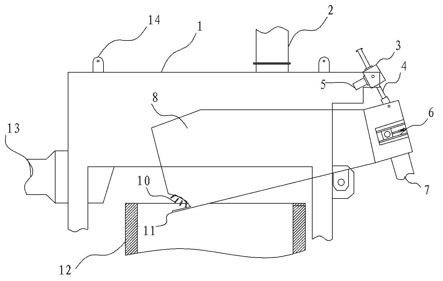
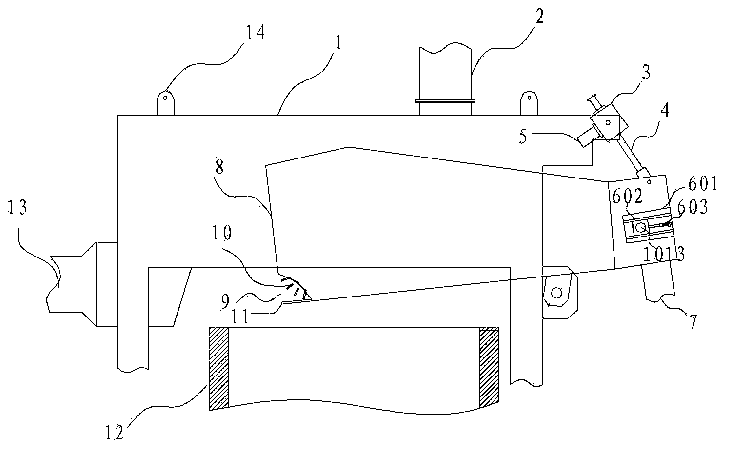
[0050] Such as figure 1 , figure 2 , Figure 4-8 As shown, a swing-type lead melting slag removal device includes a support frame 1, a slag removal box 8, a chain rake mechanism 10 inside the slag removal box 8, and a screw mechanism that drives the slag removal box 10 to turn over.
[0051] The support frame 1 is a box structure, which is erected on the lead melting pot 12. On one side of the box structure, there is a mounting rod for hinged slag removal box 8, and the other side of the slag removal box 8 is provided with a tuyere 13. The top has an air outlet 2, and the top of the support frame 1 is provided with two mutually symmetrical lifting lugs 14.
[0052] The slag removal box 8 is installed in the support frame 1, and its middle part is hinged with the installation rod on one side of the support frame 1. One end of the slag removal box 8 extends into the support frame 1, and tilts downwards into the lead melting pot 12, and extends into the The end in the lead me...
Embodiment 2
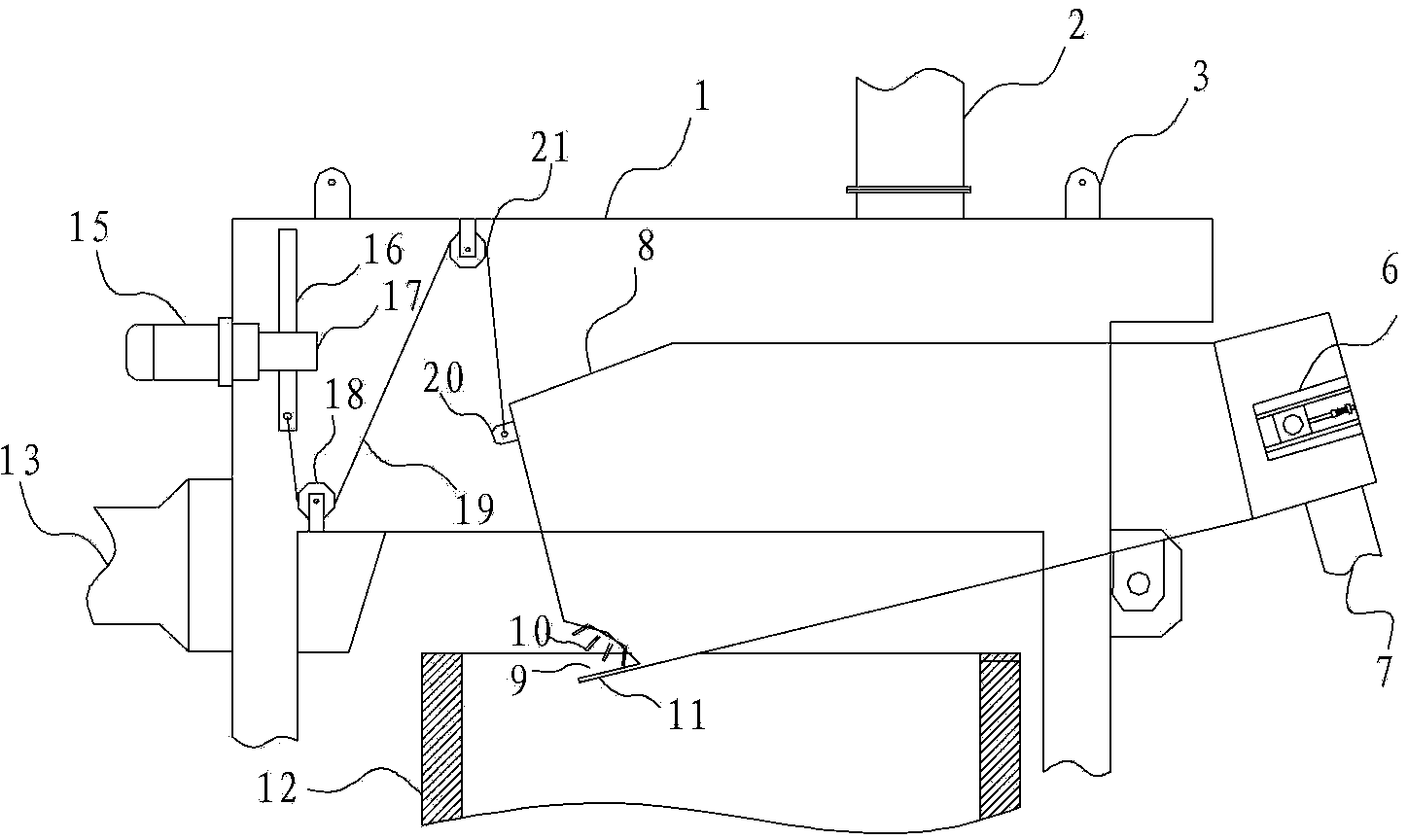
[0075] Such as 3, Figure 4-8 As shown, a swing-type lead melting slag removal device is different from Embodiment 1 in that the driving mechanism for driving the slag removal box 8 to turn over in this embodiment is different. In this embodiment, a pulley mechanism is used to drive the slag removal box 8 to swing.
[0076] The pulley mechanism is installed between the side wall of the slag opening 9 of the slag removal box 8 and the inner wall of the support frame 1. The pulley mechanism includes the second drive motor 15 installed on the support frame 1 side wall, Two fixed pulleys and the traction rope 19 that is wound on the two fixed pulleys.
[0077] A second drive motor 15 and two fixed pulleys (the first fixed pulley 18 and the second fixed pulley 21) are fixedly installed on the side wall corresponding to the slag inlet 9 of the support frame 1 and the slag removal box 8, and the second drive The output shaft of motor 15 extends into support frame 1 inside, on the in...
PUM
 Abstract
Description
Claims
Application Information
 - R&D
- Intellectual Property
- Life Sciences
- Materials
- Tech Scout
- Unparalleled Data Quality
- Higher Quality Content
- 60% Fewer Hallucinations
Browse by: Latest US Patents, China's latest patents, Technical Efficacy Thesaurus, Application Domain, Technology Topic, Popular Technical Reports.
© 2025 PatSnap. All rights reserved.Legal|Privacy policy|Modern Slavery Act Transparency Statement|Sitemap|About US| Contact US: help@patsnap.com


