Counter-flow dye vat

A dye vat and vat head technology is applied in the field of dye vats with good internal convection effect. The effect of improving the dyeing effect

Inactive Publication Date: 2015-03-04
SUZHOU AORAN COMMODITY
View PDF6 Cites 0 Cited by
  • Summary
  • Abstract
  • Description
  • Claims
  • Application Information

AI Technical Summary

Problems solved by technology

[0003] The dyeing of fabrics is generally carried out in dyeing vats. When dyeing, the fabric is put into the dyeing vats for dyeing bath. In order to make the dyeing vats reach a certain economy in general dyeing factories, the dyeing vats are often kept in a saturated state, which increases the output and maintains It is economical, but this method brings new problems. Because the fluidity of the dyes in the dyeing vat becomes poor, the places where the fabrics gather are not easy to be colored, resulting in poor fabric dyeing pass rate

Method used


Image

  • Counter-flow dye vat
  • Counter-flow dye vat

Examples


Embodiment Construction

[0015] Below in conjunction with accompanying drawing and embodiment the present invention is further described:

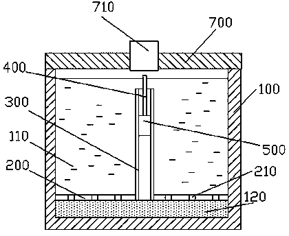
[0016] In this example, see figure 1 , the convection dyeing vat includes a dyeing vat body 100 and a vat cover 700, a circulation pipe 300 is arranged inside the dye vat body 100, and the two ends of the circulation pipe 300 are respectively located at the upper and lower parts of the dyeing vat body 100 and both ends are lower than The dye liquid surface in the dye vat body 100, the air circulation pipe 400 is arranged in the dye vat body 100, the two ends of the air circulation pipe 400 are respectively located at the upper and lower parts of the dye vat body 100 and the air circulation pipe 400 The upper end of the upper end is higher than the dye liquid level in the dye vat body 100, and both the circulation pipeline 300 and the air circulation pipeline 400 are provided with pump bodies.

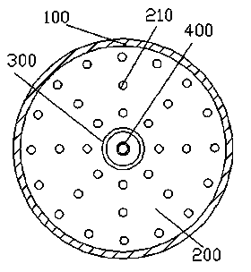
[0017] refer to figure 2 , the bottom of the dye vat body 100 is ev...


PUM


Abstract

The invention provides a counter-flow dye vat which comprises a dye vat body and a cover. A circulating pipe is arranged in the dye vat body, the two ends of the circulating pipe are positioned at the upper part and the lower part of the dye vat body respectively and are both lower than the level of a dye liquid in the dye vat body. An air circulating pipe is arranged in the dye vat body, the two ends of the air circulating pipe are positioned at the upper part and the lower part of the dye vat body respectively, and the upper end of the air circulating pipe is higher than the level of the dye liquid in the dye vat body. Liquid outlet holes are formed in the bottom of the dye vat body, the lower ends of the circulating pipe and the air circulating pipe are both connected with the liquid outlet holes. The dye liquid in the dye vat body is circulated to form counter-flows and bubbled through the circulating pipe and the air circulating pipe, and the circulating counter-flows and the bubbles rising in the dye liquid enhance the relative motion between fabrics and the dye liquid, so as to effectively improve the dyeing effect.

Description

technical field [0001] The invention relates to the field of textile dyeing and finishing equipment, in particular to a dye vat with good internal convection effect. Background technique [0002] Dyeing refers to the process in which the dye is dyed from the dye solution to the fiber and forms a uniform, firm and bright color on the fiber. The chemical composition of various fibers is different, and the applicable dyes are also different. Cotton fabrics are mainly dyed with reactive dyes. Polyester fabrics are mainly dyed with dispersed miscellaneous materials. The commonly used dyeing methods include high temperature method, carrier method and hot melting method. Modified polyester fabrics with anionic groups can also be dyed with cationic dyes to obtain rich and bright colors. Nylon fabrics are mainly dyed with acid dyes, and can also be dyed with acid mordant dyes, disperse dyes and some direct dyes at near boiling points. Acrylic fabrics are mainly dyed with cationi...

Claims


Application Information

Patent Timeline
Patent Type & Authority Patents(China)
IPC IPC(8): D06B23/14D06B3/10
Inventor 石东来
Owner SUZHOU AORAN COMMODITY
Why Eureka
Try Eureka