
Valve assembling mechanism
A technology for assembly mechanisms and valves, which is applied to assembly machines, metal processing equipment, manufacturing tools, etc., can solve the problems of time-consuming, labor-intensive, slow assembly speed, and low efficiency, and achieve the effects of cost reduction, fast assembly speed, and high efficiency
- Summary
- Abstract
- Description
- Claims
- Application Information
AI Technical Summary
Problems solved by technology
Method used
Image

Examples
Embodiment Construction
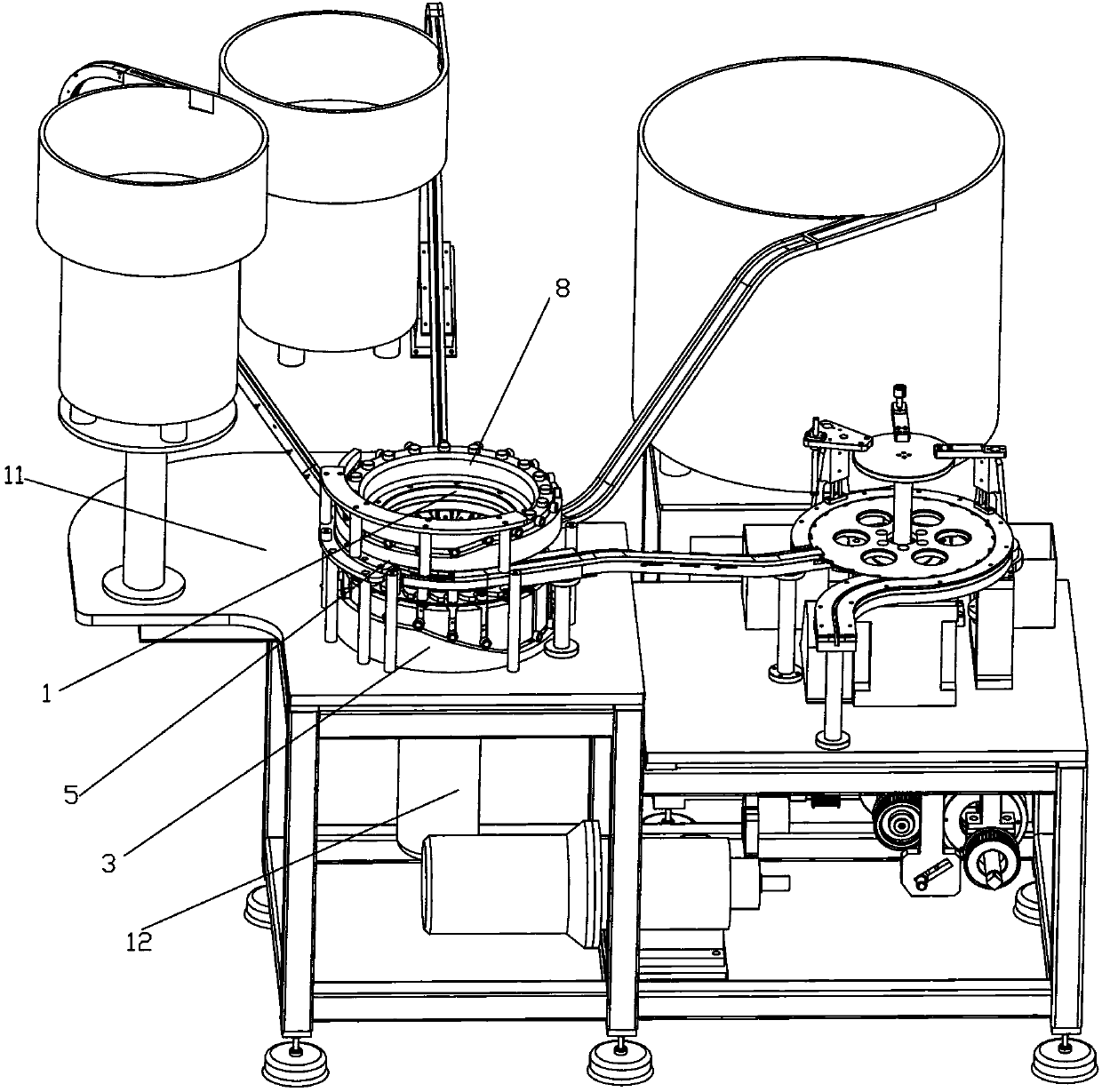
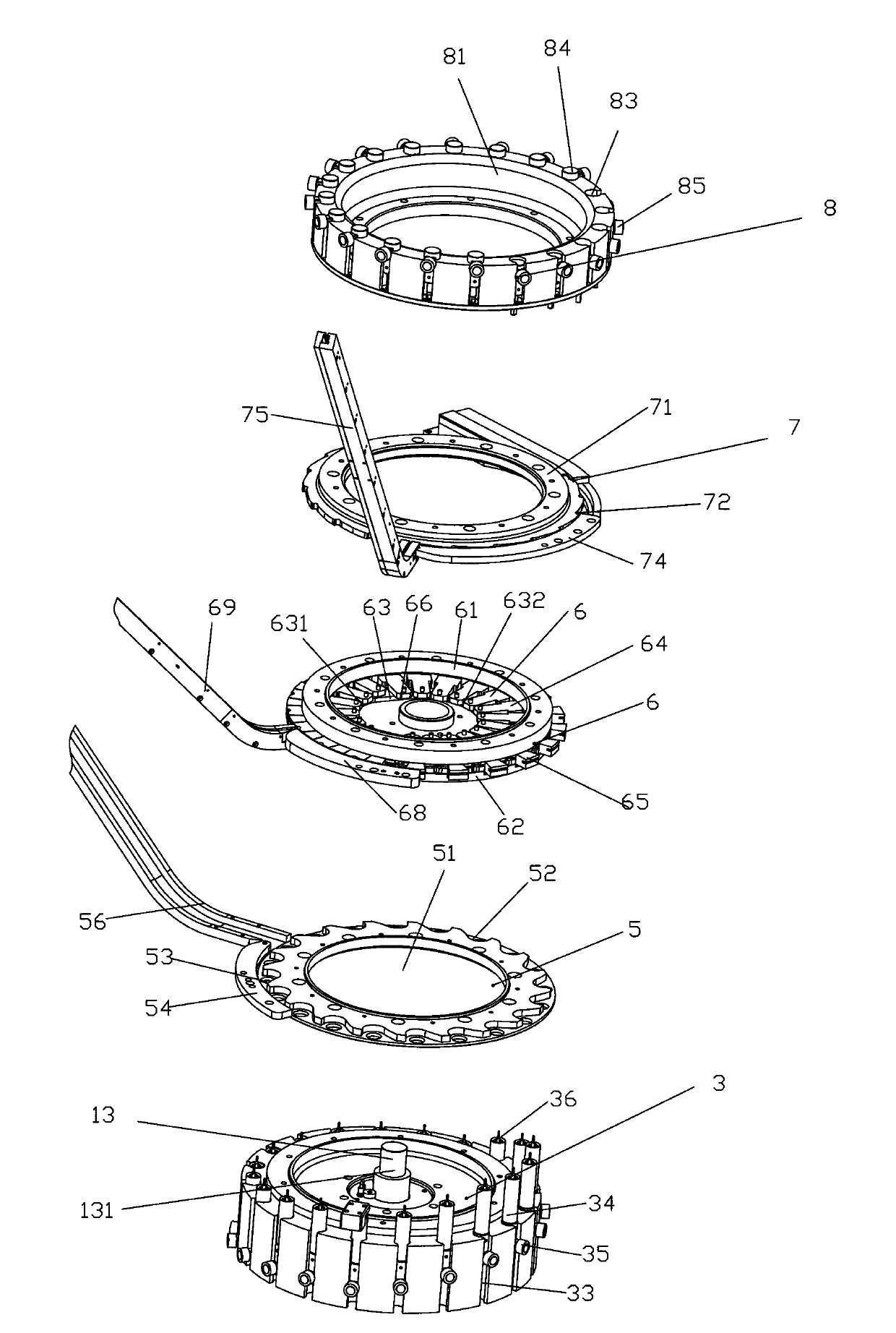
[0015] A valve assembly mechanism, which includes a main disk assembly frame 1, a drive device 12 and a transmission device 13 are arranged on the main disk assembly frame 1, and the main disk assembly frame 1 is also provided on a transmission shaft 131 of the transmission device. The lower ejector pin turntable assembly 3 , the cap feeding assembly 5 , the valve stem feeding assembly 6 , the valve nozzle feeding assembly 7 and the upper guiding ejector pin turntable assembly 8 are sequentially connected from bottom to top.
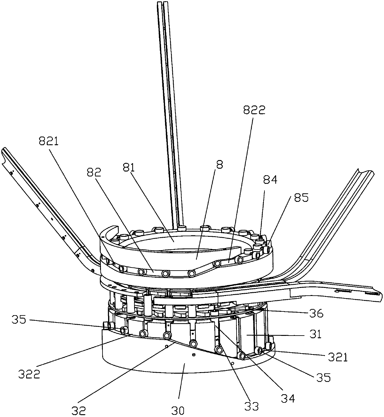
[0016] The lower push rod turntable assembly 3 includes a lower fixed disk 30, which is provided with a lower rotating disk 31 connected to the drive shaft 13 of the transmission device, and a lower roller track 32 is provided on the outer side of the lower fixed disk 30, and the lower roller track 32 includes a lower Section 321 and high section 322, the lower turntable 31 is provided with a plurality of lower ejector rod installation grooves 33, and the...
PUM
 Abstract
Description
Claims
Application Information