Large-span continuous steel truss multi-point synchronous automatic cyclic alternating sliding shoe push system and construction method thereof

A synchronous automatic, jacking construction technology, applied in the direction of bridges, bridge construction, erection/assembly of bridges, etc., can solve the problems of main structure damage, unsatisfactory non-equal cross-section main beam structure, local stress increase, etc., to avoid construction Damage and destruction, save time for manual disassembly and assembly, and improve the effect of automation

Active Publication Date: 2016-01-27
LIUZHOU OVM ENG
View PDF7 Cites 15 Cited by
  • Summary
  • Abstract
  • Description
  • Claims
  • Application Information

AI Technical Summary

Problems solved by technology

[0004] 1. Due to the large tonnage of the steel truss girder, the large reaction force of the support point, the height of the slider cannot be adjusted, the "feeding" is difficult, the local stress increases, and the damage of the slider becomes a common phenomenon, and the height of the slider cannot be adjusted. , Immediately” adjust the height to compensate for the elevation construction error and uneven settlement error of each pier and abutment, which makes the jacking process unfavorable for controlling the jacking friction resistance, increasing safety risks, and the quality of steel truss girder erection is difficult to guarantee;
[0005] 2. For the sake of safety, the designer deliberately enlarged the safety reserve during structural design, which affected the economical efficiency of construction;
[0006] 3. Temporary welding and bolting of the connection point between the fixed end of the pull-type jacking and the steel truss beam will cause construction damage to the main structure. Heavy machinery cooperates with the construction, which is extremely inconvenient for construction, and the degree of automation is not high, so it is very difficult to implement;
[0007] 4. The existing long-span steel truss girder pull-type jacking construction. The jacking and axis adjustment are independent systems. Therefore, when the axis needs to be adjusted during the jacking process, the jacking construction must be suspended, which limits the continuity and stability of the jacking construction. Controllability;
[0008] 5. The existing walking-type jacking that can be adjusted vertically cannot satisfy the main girder structure of non-uniform cross-section, especially the main girder of orthotropic slab deck structure without longitudinal girder, while the steel truss girder for joint stress It is more difficult to adapt, and it is impossible to carry out jacking construction

Method used


Image

  • Large-span continuous steel truss multi-point synchronous automatic cyclic alternating sliding shoe push system and construction method thereof
  • Large-span continuous steel truss multi-point synchronous automatic cyclic alternating sliding shoe push system and construction method thereof
  • Large-span continuous steel truss multi-point synchronous automatic cyclic alternating sliding shoe push system and construction method thereof

Examples


Embodiment 1

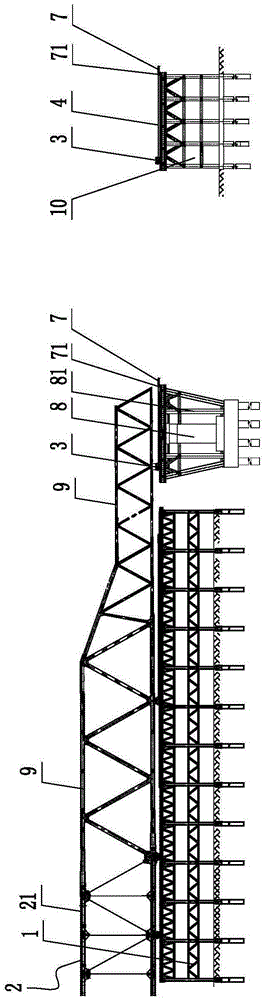
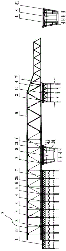
[0069] A long-span continuous steel truss girder multi-point synchronous automatic circulation alternate pushing sliding shoe pushing system, such as Figure 1-2 As shown, the long-span continuous steel truss girder multi-point synchronous automatic circulation alternate pushing sliding shoe pushing system includes: a steel truss girder assembly platform 1 for steel truss girder segmental assembly and butt joint forming, a steel guide beam 9, Temporary pier 10, push shoe 3, slideway 4 and control system;

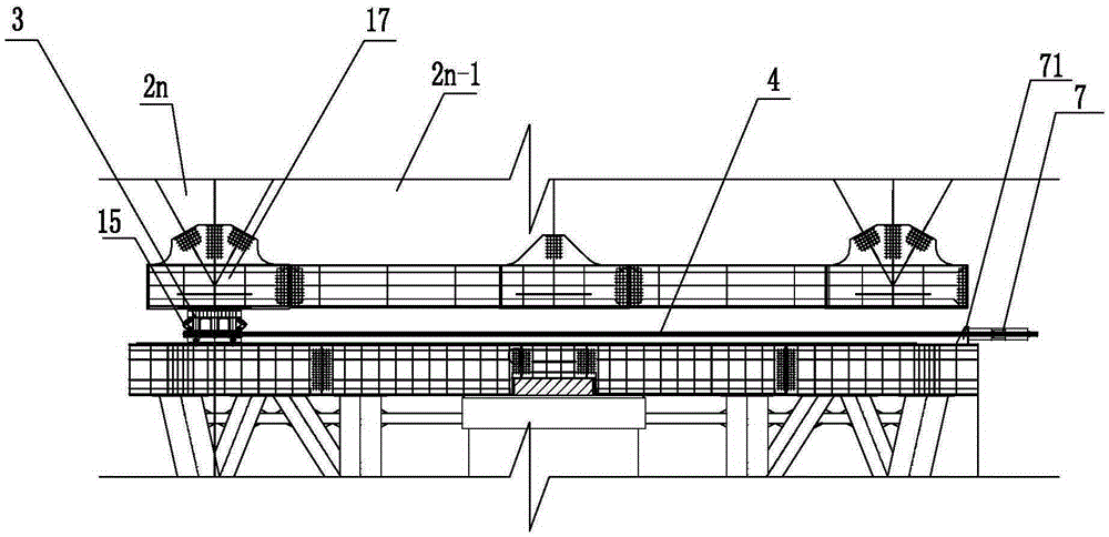
[0070] Such as image 3 As shown, the slideway includes a main slideway 41 and an auxiliary slideway 42. The main slideway 41 is also called a push slideway, which is used to bear the dead load of the steel truss girder, and the auxiliary slideway is used to bear the front and rear of the push slide shoe. Alternately, each set of slideways 4 (including the main slideway 41 and the auxiliary slideway 42) is provided with two sets of vertically adjustable pusher shoes 3, and ...

Embodiment 2

[0079] A long-span continuous steel truss girder multi-point synchronous automatic circulation alternately pushing sliding shoe jacking construction method, which is to use the long-span continuous steel truss girder multi-point synchronous automatic circulation alternating pushing sliding shoe jacking described in the first embodiment The system realizes the method of multi-point synchronous automatic circulation and alternating pushing and sliding shoe jacking construction of long-span continuous steel truss girders, including the steel truss girder assembly platform and the setting of slideways on the platform for the steel truss girders to be pieced together in sections and butt-jointed. ; The layout and design method of the jacking steel guide beams and temporary piers, as well as the design regulations and settings of the slideway on the temporary piers, steel truss beam assembly platform and permanent piers; the setting of the jacking shoes that can automatically compensa...


PUM


Abstract

The invention discloses a large-span continuous steel truss multi-point synchronous automatic cyclic alternating sliding shoe push system. The system comprises a steel truss assembling platform, push steel launching noses, temporary piers, slideways and a control system. The slideways comprise primary slideways and secondary slideways, and the primary slideways are provided with push sliding shoes capable of vertical height adjustment for installing reaction frames of continuous push jacks of push steel trusses on the front ends of the primary slideways; the two sides of each push sliding shoe are each provided with a push sliding shoe transverse jack, the continuous push jacks, the push sliding shoe transverse jacks and push sliding shoe vertical jacks form a push slip hydraulic jack system, each set of jacks are provided with a pressure sensor and a displacement sensor for detecting pressure of each jack, displacement of each hydraulic cylinder and concrete positions of the push sliding shoes; and control data of the hydro-electric control system on each slideway is fed back to a master control computer in a concentrated mode, and the computer emits control instructions to the hydro-electric control systems so as to realize push construction synchronization. The construction method is fast, safe and reliable.

Description

technical field [0001] The invention relates to bridge construction equipment and a construction method thereof, in particular to a large-span continuous steel truss girder jacking system and a construction method thereof. Background technique [0002] Steel truss is a relatively prominent bridge structure in transportation infrastructure, especially suitable for railway bridges, or road-rail bridges; for construction environments, especially in gully and canyon areas, large-span canyon bridges that are extremely inconvenient for large-scale transportation , the steel truss structure is one of the necessary structures in the industry; in terms of safety, quality, economy, etc., the construction of steel truss structure bridges with heavy weight, large span, and complex construction environment must adapt to the requirements of the times, and adopt new technologies and new processes And optimize the existing technology to serve this kind of bridge construction, and achieve th...

Claims


Application Information

Patent Timeline
Patent Type & Authority Applications(China)
IPC IPC(8): E01D21/06
Inventor 韦福堂朱廷志孙长军莫露莹刘文黄文涛张国强
Owner LIUZHOU OVM ENG
Why Eureka
Try Eureka