Tool change magazine for a motorized machine tool and machine tool

A tool replacement and machine tool technology, applied in the field of tool replacement library, to achieve the effect of cost reduction

Active Publication Date: 2013-03-27
ROBERT BOSCH GMBH
View PDF6 Cites 3 Cited by
  • Summary
  • Abstract
  • Description
  • Claims
  • Application Information

AI Technical Summary

Problems solved by technology

But what is problematic here is, for example, the perceptibility of the mentioned markings in darker ambient conditions

Method used


Image

  • Tool change magazine for a motorized machine tool and machine tool
  • Tool change magazine for a motorized machine tool and machine tool
  • Tool change magazine for a motorized machine tool and machine tool

Examples


Embodiment Construction

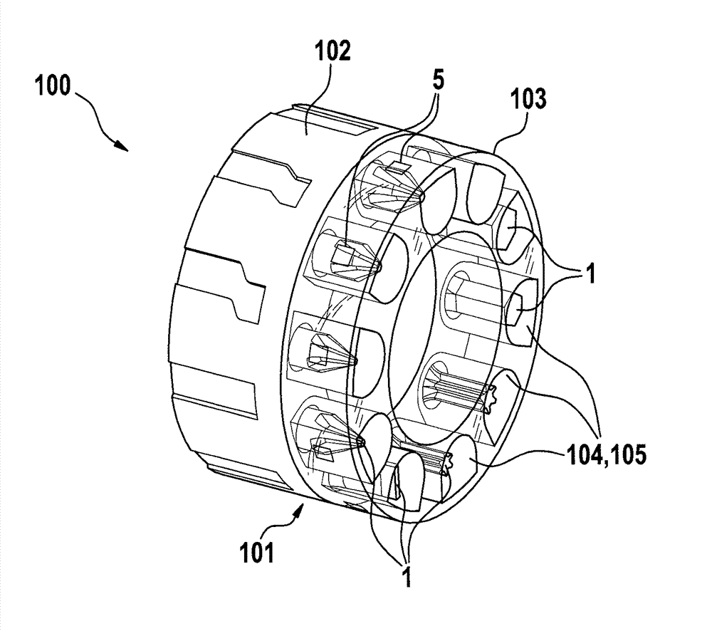
[0020] figure 1 A tool change magazine 100 according to the invention is shown. The tool changing magazine 100 has an annular or drum-shaped housing 101 rotatable along its longitudinal axis, which is divided into two parts in the longitudinal direction. The first housing part 102 is made of an opaque plastic material, while the second housing part 103 which is connected to said first housing part 102 in the longitudinal direction consists of a transparent plastic. The first housing part can be used for manual adjustment of a tool change magazine in machine tool 10 and is provided, for example, with grooves or the like for easy and precise adjustment of tool change magazine 100 for an operator. Furthermore, scratches or similar damage are not as noticeable from the outside as on housing part 103 , which is made of opaque plastic. In the interior of housing 101 , receiving openings 104 arranged at a uniform angular distance from one another are formed for receiving respective...


PUM


Abstract

The tool changing magazine (100) has a rotatable ring or drum-like housing (101) which is divided into non-transparent and transparent plastic housing portions (102,103) in longitudinal direction. The tool chambers (105) are arranged in the transparent plastic housing portion, so that insertion and removal of tools (1) into or out of retainers (104) of tool chamber is enabled. A LED light source is arranged in the housing, for illuminating the region of transparent plastic housing portion. An independent claim is included for motor-driven machine tool.

Description

technical field [0001] The invention relates to a tool changing magazine for a machine tool driven by an electric motor. Furthermore, the invention relates to a power tool driven by an electric motor. Background technique [0002] Such a tool change magazine as a component in a machine tool and a corresponding machine tool are known from DE 10 2006 059 688 A1 of the applicant. The known tool change magazine has tool pockets in which each tool is arranged. In order for the operator to find out which tool is in use or to be able to select the correct tool from the tool magazine when changing tools, the known power tool has a viewing window on the upper side of its housing. , through which the identification marks assigned to the tools in the respective tool magazines can be visually seen. However, what is problematic here is, for example, the perceptibility of the mentioned markings in darker ambient conditions. The known power tool basically requires that the marking be a...

Claims


Application Information

Patent Timeline
Patent Type & Authority Applications(China)
IPC IPC(8): B25F3/00B25B21/00
CPCB23Q3/157B23Q17/2442B25F5/029B23Q3/15534B23Q2003/1553Y10T483/14Y10T483/1783Y10T483/1798Y10T483/18Y10T483/1827Y10T483/1882B23Q3/15706B23Q3/15766B25F1/04B25H3/003F21V33/0084
Inventor A.纳吉H.黑泽
Owner ROBERT BOSCH GMBH
Why Eureka
Try Eureka