Power transmission for sweeping vehicles
A power transmission device and cleaning vehicle technology, which is applied in road cleaning, cleaning methods, construction, etc., can solve the problems of high use cost, large exhaust emissions, and large fuel consumption, so as to reduce fuel consumption and use cost, and reduce pollution , the effect of reducing emissions
- Summary
- Abstract
- Description
- Claims
- Application Information
AI Technical Summary
Problems solved by technology
Method used
Image

Examples
Embodiment 1
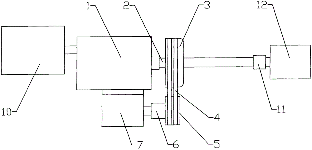
[0023] Embodiment 1: as attached figure 1 As shown, the power transmission device for the sweeping vehicle includes an engine 10, a transmission 1, a differential 12, a hydraulic motor 7 and a transmission shaft 2, the engine 10 is connected to the transmission 1, and the transmission shaft 2 is respectively connected to the transmission 1 and the differential Gear 12 is connected in transmission, a shaft coupling 11 is arranged between the transmission shaft 2 and the differential 12, a brake drum 3 is arranged on the transmission shaft 2, and the hydraulic motor 7 is connected in transmission with the transmission shaft 2.
[0024] The outer circumference of the brake drum 3 is provided with a pulley groove, the output shaft of the hydraulic motor 7 is provided with a driving pulley 5, and the driving pulley 5 and the brake drum 3 are provided with a belt 4, between the driving pulley 5 and the hydraulic motor 7 A clutch 6 is provided.
[0025] Clutch 6 is an electromagneti...
Embodiment 2
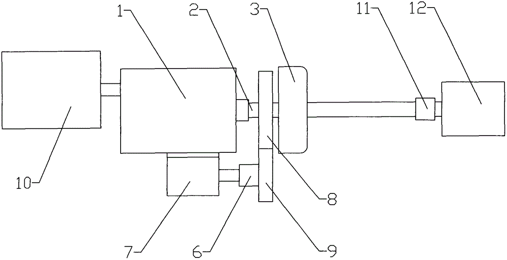
[0027] Embodiment 2: as attached figure 2 As shown, the transmission shaft 2 is provided with a first gear 8, the output shaft of the hydraulic motor 7 is provided with a second gear 9, the first gear 8 and the second gear 9 mesh, and the hydraulic motor 7 and the second gear 9 are arranged With clutch 6.
[0028] Clutch 6 is an electromagnetic clutch.
[0029] The first gear 8 is located between the transmission 1 and the brake drum 3 .
[0030] The first gear 8 is a sliding gear, and the engagement and disengagement of the first gear 8 and the second gear 9 are realized by controlling the position of the first gear 8 .
[0031] Other structures are the same as in Embodiment 1.
[0032] When the vehicle moved forward, the engine 10 worked, and the cleaning engine did not work; when cleaning, the engine 10 did not work, and the cleaning engine and the hydraulic motor 7 worked, and the hydraulic motor 7 drove the second gear 9 to rotate, and the second gear 9 drives the fi...
Embodiment 3
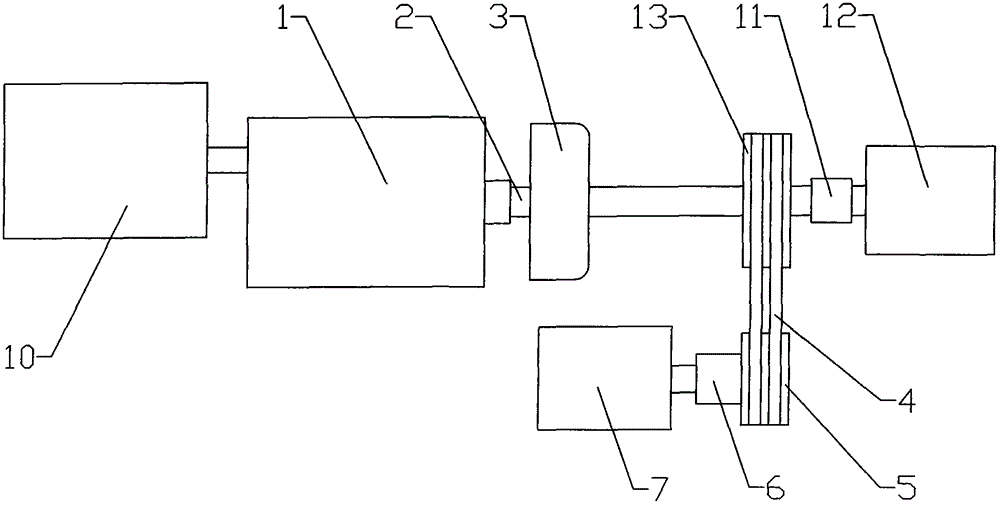
[0033] Embodiment 3: as attached image 3 As shown, the output shaft of the hydraulic motor 7 is provided with a driving pulley 5, the transmission shaft 2 is provided with a driven pulley 13, the driving pulley 5 and the driven pulley 13 are provided with a belt 4, the driving pulley 5 and A clutch 6 is provided between the hydraulic motors 7 .
[0034] Clutch 6 is an electromagnetic clutch.
[0035] The driven pulley 13 is located at a position close to the differential 12 .
[0036] Other structures are the same as in Embodiment 1.
[0037] When the vehicle moved forward, the engine 10 worked, and the cleaning engine did not work; when cleaning, the engine 10 did not work, and the cleaning engine and the hydraulic motor 7 worked, and the hydraulic motor 7 drove the driving pulley 5 to rotate, and the driving pulley 5 Drive the driven pulley 13 to rotate through the belt 4, and the driven pulley 13 drives the transmission shaft 2 to rotate, thereby driving the vehicle to ...
PUM
 Abstract
Description
Claims
Application Information