Rotary fire grate

A technology of rotating grates and grates, which is applied in the direction of incinerators, combustion methods, combustion types, etc., and can solve problems such as being easily blocked between the grates or stuck in the slagging hole, burning out the motor, and unsmooth slagging.

Active Publication Date: 2013-03-27
宁波泰来环保设备有限公司
View PDF5 Cites 13 Cited by
  • Summary
  • Abstract
  • Description
  • Claims
  • Application Information

AI Technical Summary

Problems solved by technology

The existing fire grate is an eccentric integral fire grate, which is composed of three eccentric forward rotating active fire grates, the first forward rotating driven fire grate, and the second forward rotating driven fire grate welded to the main shaft sleeve. The positive rotating active grate, the first forward rotating driven grate and the second forward rotating driven grate are all equipped with slag discharge holes, and the integral rotary grate is driven by the motor to rotate, and the slag is removed from the furnace under the action of eccentric force. The furnace body is discharged from the slag discharge hole, but the existing grate has the following disadvantages: First, large slagging and hard objects are prone to appear in the garbage incineration. Hard slag objects are easily blocked between the grates or stuck in the slag discharge hole, resulting in unsmooth slag discharge; and the overall resistance of the grate is large, and the grate is likely to be stuck and burn out the motor or reducer; the second is that the combustion air passes through the exhaust After the slag hole enters the air from the slagging hole of the grate and the gap between the grates, it is fully mixed with the garbage material. If a large slagging hard object is blocked between the grates or stuck in the slagging hole, it will affect the combustion air intake. The amount of combustion air intake is small, which affects the mixing effect of combustion air and garbage

Method used


Image

  • Rotary fire grate
  • Rotary fire grate
  • Rotary fire grate

Examples


Embodiment Construction

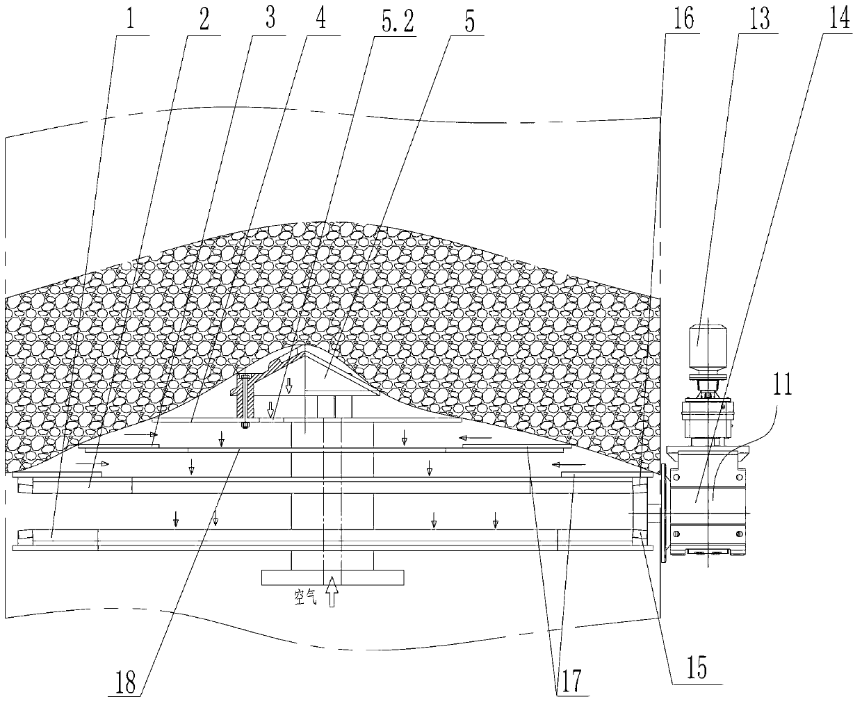
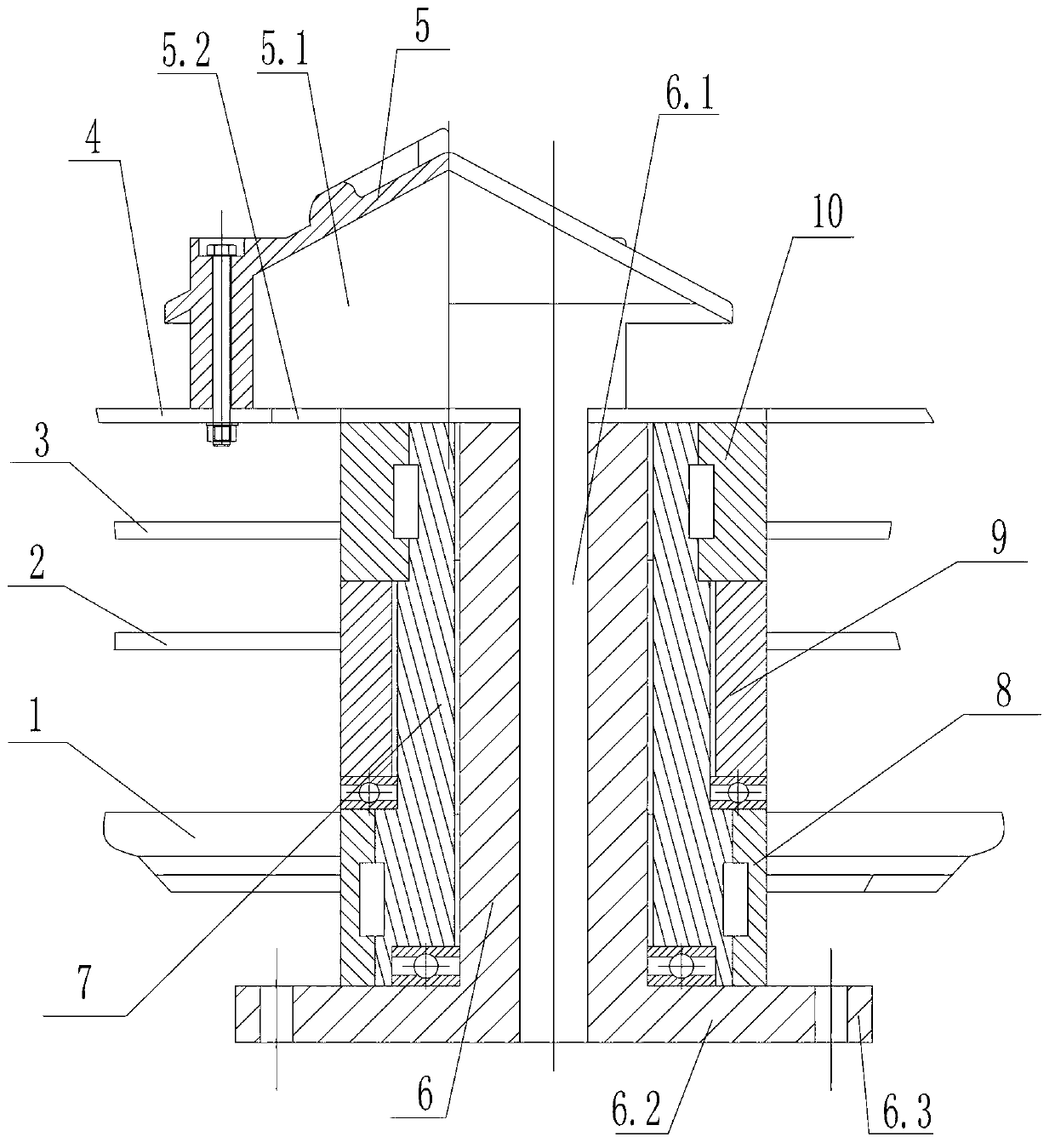
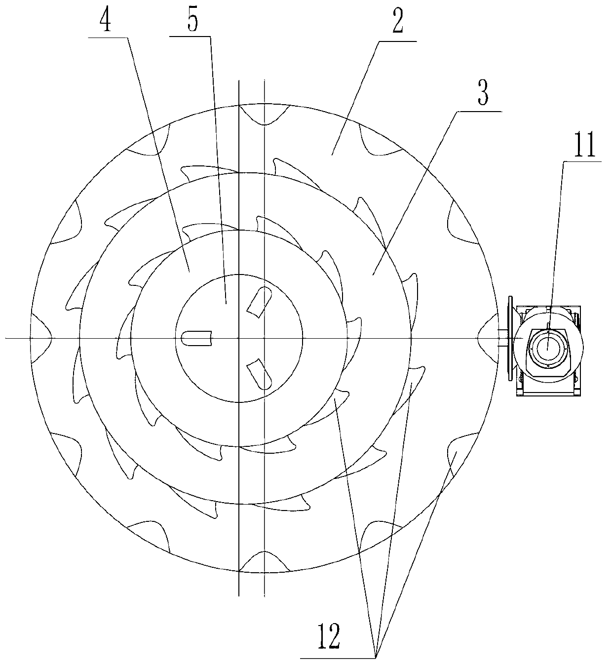
[0020] The present invention will be further described below in conjunction with the accompanying drawings and specific embodiments.

[0021] see figure 1 , figure 2 , image 3 with Figure 4 As shown, the rotary fire grate of the present invention includes a fixed shaft 6, a main shaft sleeve 7, a first positively rotating driven fire grate 3, a second positively rotating driven fire grate 4 and a forwardly rotating active fire grate connected with a drive mechanism 11 1. The forward-rotating active grate 1, the first forward-rotating driven grate 3, and the second forward-rotating driven grate 4 are all provided with slagging holes 18, and the forward-rotating active grate 1, the first Both the forward rotating driven grate 3 and the second forward rotating driven grate 4 are fixedly connected with the main shaft sleeve 7, and the main shaft sleeve 7 is movably socketed with the fixed shaft 6, and it also includes a reverse active fire grate 2, the Forward-rotating acti...


PUM


Abstract

The invention relates to a rotary fire grate which comprises a fixed shaft, a main shaft sleeve, a first forward driven fire grate, a second forward driven fire grate and a forward driving fire grate connected with a driving mechanism. The forward driving fire grate, the first forward driven fire grate and the second forward driven fire grate have slag removing holes. The forward driving fire grate, the first forward driven fire grate and the second forward driven fire grate are fixedly connected with the main shaft sleeve which is movably sleeved with the fixed shaft. The rotary fire grate further comprises a reverse driving fire grate. The forward driving fire grate, the reverse driving fire grate, the first forward driven fire grate and the second forward driven fire grate are arranged sequentially from bottom to top and distances are reserved between adjacent fire grates. The forward driving fire grate is connected with the driving mechanism, the reverse driving fire grate is movably sleeved with the main shaft sleeve, and the reverse driving fire grate has a slag removing hole. The rotary fire grate is good in slag breaking effect and smooth in slag discharge.

Description

technical field [0001] The invention belongs to the technical field of solid waste treatment engineering, and in particular relates to a rotary grate of a vertical pyrolysis gasification furnace. Background technique [0002] The vertical pyrolysis gasification incinerator is a new type of waste treatment equipment. Although it appeared relatively late in the waste treatment industry, it has received more and more attention due to its compact structure, low operating cost, and good tail gas emission effect. application, and with the increasing improvement of technology, the vertical pyrolysis gasification incinerator will become an important choice for small and medium domestic waste incineration power plants in the future. The grate is the core component of the vertical pyrolysis gasification incinerator. The grate mainly plays the following functions: one is the support function, holding up the garbage material to make the garbage material burn, pyrolyze and gasify in the ...

Claims


Application Information

Patent Timeline
Patent Type & Authority Applications(China)
IPC IPC(8): F23G5/44
Inventor 刘玉山鲍海明俞勐海
Owner 宁波泰来环保设备有限公司
Why Eureka
Try Eureka