How to measure the focal length of a convex lens

A measurement method, convex lens technology, applied in the direction of testing optical performance, etc., can solve the problems of inaccurate measurement of image distance, error of lens focal length, inaccurate measurement of object distance, etc., achieve accurate object distance and image distance, eliminate human error, and facilitate observed effect

Inactive Publication Date: 2016-03-30
JILIN UNIV
View PDF6 Cites 0 Cited by
  • Summary
  • Abstract
  • Description
  • Claims
  • Application Information

AI Technical Summary

Problems solved by technology

[0004] The disadvantage of the method for measuring the focal length of the lens is that the object distance and the image distance are not easy to measure accurately.
First of all, it is difficult to determine that the position of the optical bench that fixes the two lasers is the intersection point of the reverse extension of the two laser beams, so the measurement of the object distance is inaccurate; in addition, the laser spot on the whiteboard is very large. It is difficult to judge whether the two laser beams are irradiated on the same point of the whiteboard, resulting in very inaccurate measurement of image distance
Therefore, there is a large error in the lens focal length calculated from the object distance and image distance obtained according to the above technical solution.

Method used


Image

  • How to measure the focal length of a convex lens
  • How to measure the focal length of a convex lens
  • How to measure the focal length of a convex lens

Examples


Embodiment Construction
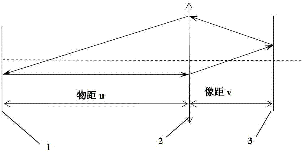
[0023] The inventive idea of ​​the present invention is: use the light emitted by a laser and the light reflected by the plane mirror to form a light circuit, and the small holes on the hole screen and the light spots on the plane mirror can be regarded as equivalent objects and images.

[0024] The present invention will be described in detail below in conjunction with the accompanying drawings.

[0025] The measuring method of convex lens focal length of the present invention comprises the following steps:

[0026] 1. Place the laser, hole screen 1, convex lens 2, and plane mirror 3 on the light guide rail, and adjust the coaxiality; the laser light emitted by the laser can pass through the small hole on the hole screen 1.

[0027] 2. Fine-tune the horizontal direction of the slider on the optical bench where the convex lens 2 is installed, so that the horizontal direction of the convex lens 2 is a certain distance away from the axis. On the basis of ensuring that the experi...


PUM


Abstract

The invention relates to a method for measuring the focal distance of a convex lens, comprising the following steps: setting a laser, a hole shield, a convex lens, a plane mirror and an adjusting common axis, wherein the laser light emitted by the laser can pass through a small hole on the hole shield; adjusting the vertical position of the convex lens so as to have a certain distance from a shaft; adjusting the position of the plane mirror, so that the laser light emitted from the small hole of the hole shield is refracted through a lens and then reflected through the plane mirror, and the light is then refracted through the convex lens to return into the small hole on the hole shield so as to form closed light; and calculating to obtain the focal distance of the convex lens by using the distance between the hole shield and the convex lens as an object distance or an image distance and using the distance between the plane mirror and the convex lens. According to the method for measuring the focal distance of the convex lens provided by the invention, artificial errors are eliminated well, and the result of the focal distance of the convex lens obtained through the calculation is very accurate since the object distance and the image distance determined by the hole shield and the plane mirror are both accurate.

Description

technical field [0001] The invention relates to the technical field of measuring the property parameters of a convex lens, in particular to a method for measuring the focal length of a convex lens. Background technique [0002] Convex lens is the most commonly used optical element and is the basis of optical instruments such as microscopes and telescopes. The focal length is an important parameter to characterize the imaging properties of the lens. Determining the focal length is not only a product inspection task, but more importantly, it provides a basis for the design of the optical system. [0003] The most commonly used focal length measurement methods are mostly designed according to the relationship between the object and the image, such as the object distance and image distance method. Specifically, this method is based on the fact that the light emitted by the object will form a real image on the other side after being converged by a convex lens, and then in the li...

Claims


Application Information

Patent Timeline
Patent Type & Authority Patents(China)
IPC IPC(8): G01M11/02
Inventor 韩力刘铁成刘春杰
Owner JILIN UNIV
Why Eureka
Try Eureka