
Image display device for vehicle and method for displaying rapid changed image inputted from camera for vehicle

An image display device and image change detection technology, which is applied in image analysis, image data processing, optical observation devices, etc., can solve the problems that drivers cannot quickly identify rapid changes, cannot improve driving safety, and do not support display functions.

Inactive Publication Date: 2013-03-27
HYUNDAI MOBIS CO LTD
View PDF3 Cites 4 Cited by
  • Summary
  • Abstract
  • Description
  • Claims
  • Application Information

AI Technical Summary

Problems solved by technology

[0005] but if figure 1 As shown, the traditional vehicle image display device only displays the images obtained by the camera showing the front, rear and side conditions of the vehicle as they are, and does not support the display function of highlighting the rapidly changing parts of the image to attract the driver's attention
That is to say, the traditional vehicle image display device can enable the driver to confirm the surrounding conditions of the vehicle in real time, but when an object suddenly appears in the field of view of the camera, it still continues to display the image, and cannot make use of other additional display functions. Quick and accurate identification
[0006] All in all, the traditional vehicle image display device is that the driver cannot quickly recognize the rapid changes in the image during driving by using the image display function, and cannot improve driving safety.

Method used


Image

  • Image display device for vehicle and method for displaying rapid changed image inputted from camera for vehicle
  • Image display device for vehicle and method for displaying rapid changed image inputted from camera for vehicle
  • Image display device for vehicle and method for displaying rapid changed image inputted from camera for vehicle

Examples


Embodiment Construction

[0021] An embodiment of the present invention will be described in detail below with reference to the accompanying drawings.

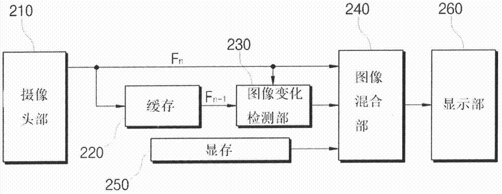
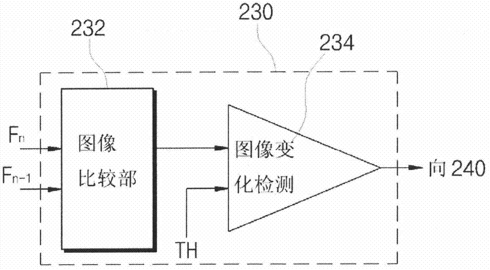
[0022] figure 2 is a diagram of a vehicle imaging device according to an embodiment of the present invention, image 3 yes figure 2 Internal configuration diagram of the image change detection unit shown in .

[0023] refer to figure 2 , the vehicle image display device in one embodiment of the present invention includes a camera section 210 , a buffer 220 , an image change detection section 230 , an image mixing section 240 , and a video memory 260 .

[0024] Structurally, the camera section 210 outputs the input image comprising the previous image and the current image (Fn) in frame units, including a front camera for shooting the front area and outputting the front image; a rear camera for shooting the rear area of ​​the vehicle and outputting the rear image; and shooting the vehicle The side area inputs the side camera for the side image.

...


PUM


Abstract

The present invention detects rapid change within an image inputted from a camera for a vehicle, and facilitates a driver to accurately identify a part needing to be grasped focally in the image by using the image to display the rapid changed part in the image, thereby rapidly identifying the rapid changed image in the image during driving of the vehicle by using an image display function, and contributing to raise of safety of the driving.

Description

technical field [0001] The invention relates to a vehicle image display system, in particular to a vehicle image display system for highlighting rapidly changing areas of images input from a vehicle camera and a display method for rapidly changing images input from the vehicle camera. Background technique [0002] The image display device equipped in the car is a device that obtains peripheral images showing the surrounding conditions of the vehicle through a camera and provides them to the driver through a display device such as an LCD. figure 1 It is a conventional image display device in a car. [0003] figure 1 It is a structural diagram of a conventional in-vehicle image display device. [0004] refer to figure 1 , the traditional vehicle image display device is installed in the prescribed position of the vehicle 10, and its composition includes: a camera 20 for photographing the front peripheral field, the side peripheral fields and the rear peripheral field; conver...

Claims


Application Information

Patent Timeline
IPC IPC(8): H04N7/18G06K9/00B60R1/00
CPCB62D15/0275G06T7/248G08G1/166
Inventor 张赈
Owner HYUNDAI MOBIS CO LTD
Learn More