Method for reducing the drive slip in vehicles with multiple engines

A technology of motors and vehicles, which is applied to the arrangement of multiple different prime movers, vehicle components, brakes, etc. of general power plants, and can solve the problems of signal transmission consumption, damage to ASR-regulation, and inability to provide real-time signal values, etc.

Inactive Publication Date: 2013-03-27
ROBERT BOSCH GMBH
View PDF5 Cites 0 Cited by
  • Summary
  • Abstract
  • Description
  • Claims
  • Application Information

AI Technical Summary

Problems solved by technology

In contrast, in vehicles with one or more electric motors, the ASR regulation is relatively slow because the signal transmission and signal processing are complex
Delays or dead times (Totzeit) therefore occur, during which no real-time signal values ​​are available and which impair the ASR-regulation
Therefore, ASR-regulation is not optimal in vehicles with electric motors (EN)

Method used


Image

  • Method for reducing the drive slip in vehicles with multiple engines

Examples


Embodiment Construction

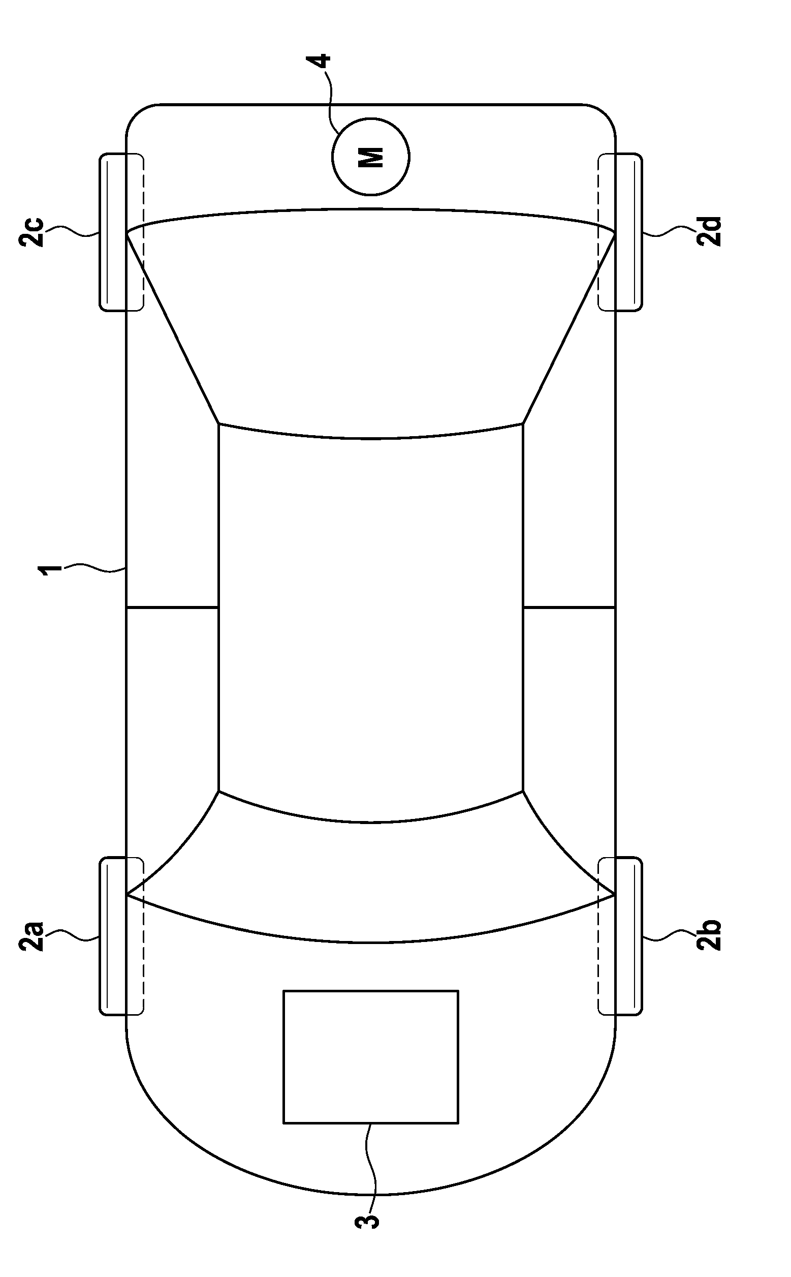
[0013] figure 1 A vehicle 1 is shown in a schematic block diagram with an internal combustion engine 3 for driving the front axle and an electric motor 4 for driving the rear axle. The wheels of the front axle are marked with 2a, 2b, the wheels of the rear axle with 2c, 2d.

[0014] In order to reduce the drive slip of the wheels 2 a - 2 d during acceleration, it is provided that slip regulation is carried out at the front wheels 2 a , 2 b and slip control is carried out at the rear wheels.

[0015] The coefficient of friction [mu] is estimated in a conventional manner when the slip adjustment is carried out at the front wheels 2a, 2b. From this, the drive torque for the electric motor 4 can be calculated, which can be maximized on the road surface. The electric motor 4 is now controlled in such a way that it produces a portion of the maximum achievable drive torque. The proportion of the drive torque that can be formed can be, for example, between 80% and 90%, or even less...


PUM


Abstract

The invention relates to a method for reducing the drive slip of vehicle wheels which are driven by different engines (3, 4). The drive slip can be set in a particularly easy and cost-effective way if a slip control process is carried out at a first group of wheels (2a, 2b) which are driven by a first engine (3), and the drive torque is controlled at a second group of wheels (2c, 2d) which are driven by a second engine (4).

Description

technical field [0001] The invention relates to a method for reducing drive slip of vehicle wheels driven by different motors. Background technique [0002] When the vehicle is accelerating, the following situation arises: If the drive torque is too high compared to the coefficient of friction, the individual wheels will be in drive slip. Various slip regulators (ASR drive anti-skid systems) are known from the prior art, with which the wheel speed of a slipping wheel is adjusted to a reference speed. The reference speed is generally referred to here as the vehicle speed or the speed of the spinning wheels. In vehicles with an internal combustion engine, the ASR control is relatively unproblematic. In contrast, in vehicles with one or more electric motors, the ASR regulation is relatively slow, since signal transmission and signal processing are complex. Time delays or dead times (Totzeit) therefore occur, during which no real-time signal values ​​are available and which i...

Claims


Application Information

Patent Timeline
Patent Type & Authority Applications(China)
IPC IPC(8): B60T8/175B60T8/172B60W10/06B60W10/08B60K6/52
CPCB60L2240/423B60W30/18172B60K28/16B60W10/06Y02T10/642B60W10/08B60W2520/26B60W2710/083B60W2552/40Y02T10/64
Inventor J.伦茨H.巴特尔斯
Owner ROBERT BOSCH GMBH
Why Eureka
Try Eureka